Apparatus for Seeding a Fluid with Tracing Material

a technology of tracing material and apparatus, which is applied in the direction of lift valves, mixers, instruments, etc., can solve the problems that liquid droplets, smoke, solid carbon dioxide cannot be used as tracers, and the type of seeder cannot control the seeding rate in a flow

Inactive Publication Date: 2014-11-13
UNIVERSITY OF MANITOBA
View PDF0 Cites 14 Cited by
  • Summary
  • Abstract
  • Description
  • Claims
  • Application Information

AI Technical Summary

Benefits of technology

[0028]a valve member received within the valve body and being movable relative to the valve opening in an axial direction of the outlet opening so as to adjust an effective size of the valve opening.

Problems solved by technology

In combusting flows, seeding particles such as liquid droplets, smokes, and solid carbon dioxide cannot be used as tracers.
However, there are still several practical problems associated with solid powders / particles due to the agglomeration of particles and also due to the difficulty in maintaining a steady supply of seeding particles, especially at low flow rates.
A seeder using solid carbon dioxide particles is much cleaner since these particles evaporate (no deposit) but it cannot be used in combusting flows due to the high temperature and its interference with the composition of the flow.
The size of these particles for higher velocity and turbulent measurements is relatively large and so controlling the size of these particles along the flow field is a challenge for these types of seeders [8,9].
However, this type of seeder does not have control over the seeding rate in a flow; that is, the concentration of seeding particles in the flow depends on the volumetric flow rate.
However, the concentration of particles is low and it can only be used in seeding the type of fuels where the solvent is the combusting fuel.
Moreover, as seeding particles are being consumed, the distance between the air inlet into the cyclone and the location of the particles increases which consequently leads to a change in the seeder performance [1-3].
The problem with this seeder is that the moisture content of the gas flow affects its performance drastically due to the agglomeration of particles.
Moreover, this seeder's performance deteriorates at lower flow rate ranges due to a low concentration of particles and at high flow rates due to the formation of larger particles as a result of agglomerates which in turn increases the clogging phenomenon [1,5,10].
However, it has a limited operation range in comparison with simple fluidized bed described earlier [1].
This seeder has relatively less sensitivity to the moisture content of the incoming gas but the moisture content still affects significantly its performance [5,6].
Moreover, similar to the aforementioned fluidized-bed seeders, it has a limited flow rate operating range.
This seeder has the advantage of controlling the amount of particles into the flow but is still unable to provide a steady supply at low flow rates.
However, this technique has a limited operating range as it is flow rate dependent [1,12].
Since a sonic orifice seeder has no moving parts it does not require any maintenance; however, controlling the flow rate is limited to downstream pressure [10].
Since the particles have a sharp turn at the exit of the valve after a few runs the sharp turn may cause clogging problems and thus the valve needs to be cleaned regularly [5].

Method used


Image

  • Apparatus for Seeding a Fluid with Tracing Material
  • Apparatus for Seeding a Fluid with Tracing Material
  • Apparatus for Seeding a Fluid with Tracing Material

Examples


Embodiment Construction

Design of a New Seeder

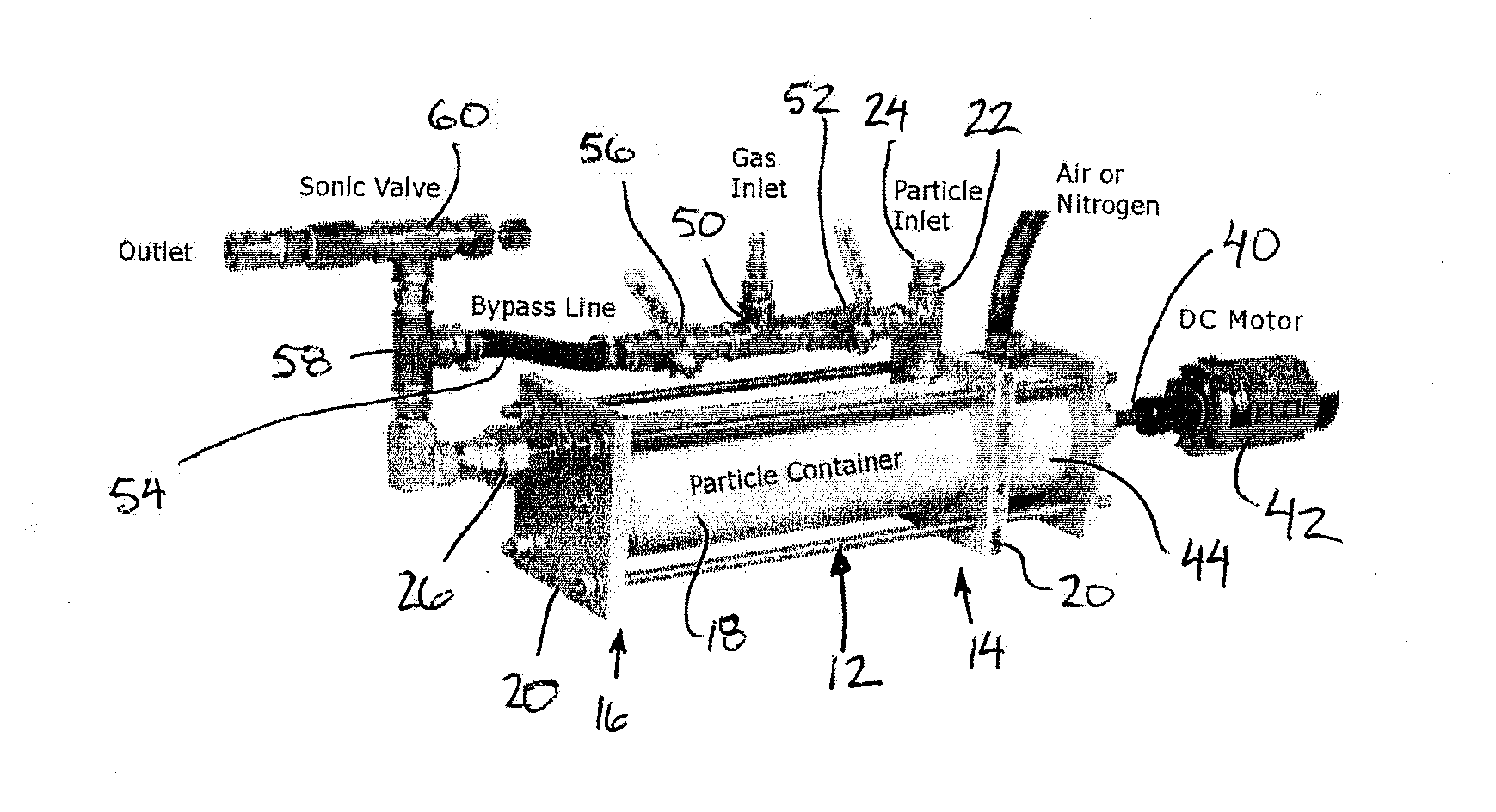
[0059]Referring initially to FIGS. 4 and 5, there is illustrated a seeding apparatus generally indicated by reference numeral 10. The apparatus 10 is particularly suited for seeding a tracing material, for example micro sized particulate material into a carrier fluid, for example a gas flow.

[0060]The apparatus 10 includes a seeding chamber 12 which generally cylindrical and elongate in a horizontal direction to extend axially between an inlet end 14 and an outlet end 16. The chamber is bound by an outer cylindrical wall 18 spanning horizontally in the longitudinal direction of the chamber between end walls 20 at the inlet and the outlet ends respectively.

[0061]An inlet coupling 22 is mounted in communication with the seeding chamber through the outer wall 18 at the top side thereof adjacent the inlet end of the chamber. The inlet coupling 22 is arranged to introduce the flow of carrier fluid into the seeding chamber in operation. When not in operation, the inle...


PUM


Abstract

A new seeder for laser-based velocity measurements in gaseous combusting and non-combusting flows is described herein. The performance of the seeder was tested under a variety of flow rate conditions. The testing revealed that control over the concentration of seeding particles, stability of particles supply, extended range of flow rate, and breakup of the agglomerates makes the newly designed seeder advantageous over its counterparts, especially for weak flow rates applications.

Description

FIELD OF THE INVENTION[0001]The present invention relates to an apparatus for seeding a tracing material, for example micro-particles, into a carrier fluid, for example a flow of gas, using a seeding chamber having a sump area for receiving the tracing material and a flow area above the sump area for receiving a flow of the carrier fluid across the tracing material in the sump area. More particularly, the present invention relates to a seeding apparatus used in laser-based velocity measurements in flames. The present invention further relates to a sonic valve for use with the seeding apparatus.BACKGROUND[0002]Measurement of fluid dynamics characteristics using non-intrusive laser-based techniques, such as particle image velocimetry (PIV) and laser Doppler velocimetry (LDV), requires seeding the fluid with micro-sized particles. These particles, which act as tracing material for the fluid motion, must have proper size and concentration / density in a flow field. Tracers should also be ...

Claims


Application Information

Patent Timeline
Patent Type & Authority Applications(United States)
IPC IPC(8): F16K1/38B01F15/02
CPCF16K1/385B01F15/02G01P5/20B01F27/0721B01F27/0724B01F27/092B01F27/11251B01F27/70B01F35/71
Inventor BIROUK, MADJIDSAEDIAMIRI, MEGHDADKOZINSKI, JANUSZ A.
Owner UNIVERSITY OF MANITOBA
Why Eureka
Try Eureka