Multi-core fiber

Active Publication Date: 2014-11-13
THE FUJIKURA CABLE WORKS LTD +1
View PDF1 Cites 227 Cited by
  • Summary
  • Abstract
  • Description
  • Claims
  • Application Information

AI Technical Summary

Benefits of technology

[0035]As described above, according to the present invention, there is provided a multi-core fiber that can suppress the crosstalk betw

Problems solved by technology

The state repeatedly occurs or continues for a long time, and the cros

Method used


Image

  • Multi-core fiber
  • Multi-core fiber
  • Multi-core fiber

Examples


first embodiment

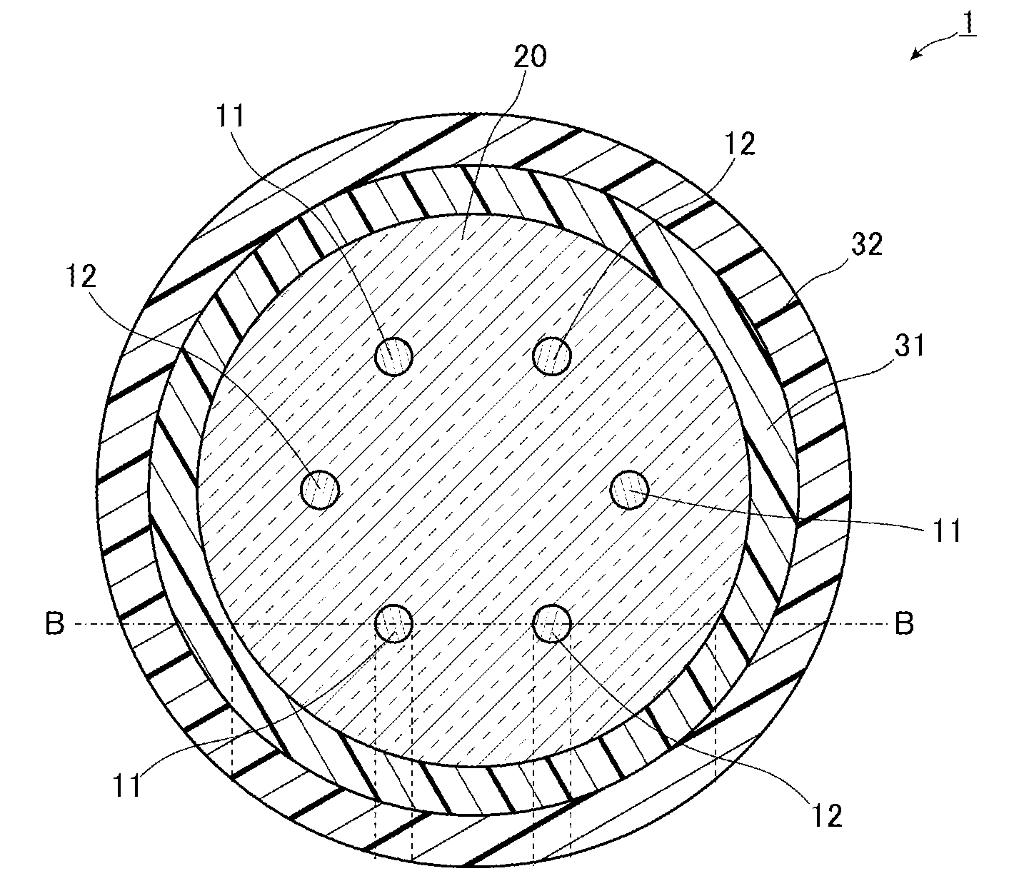
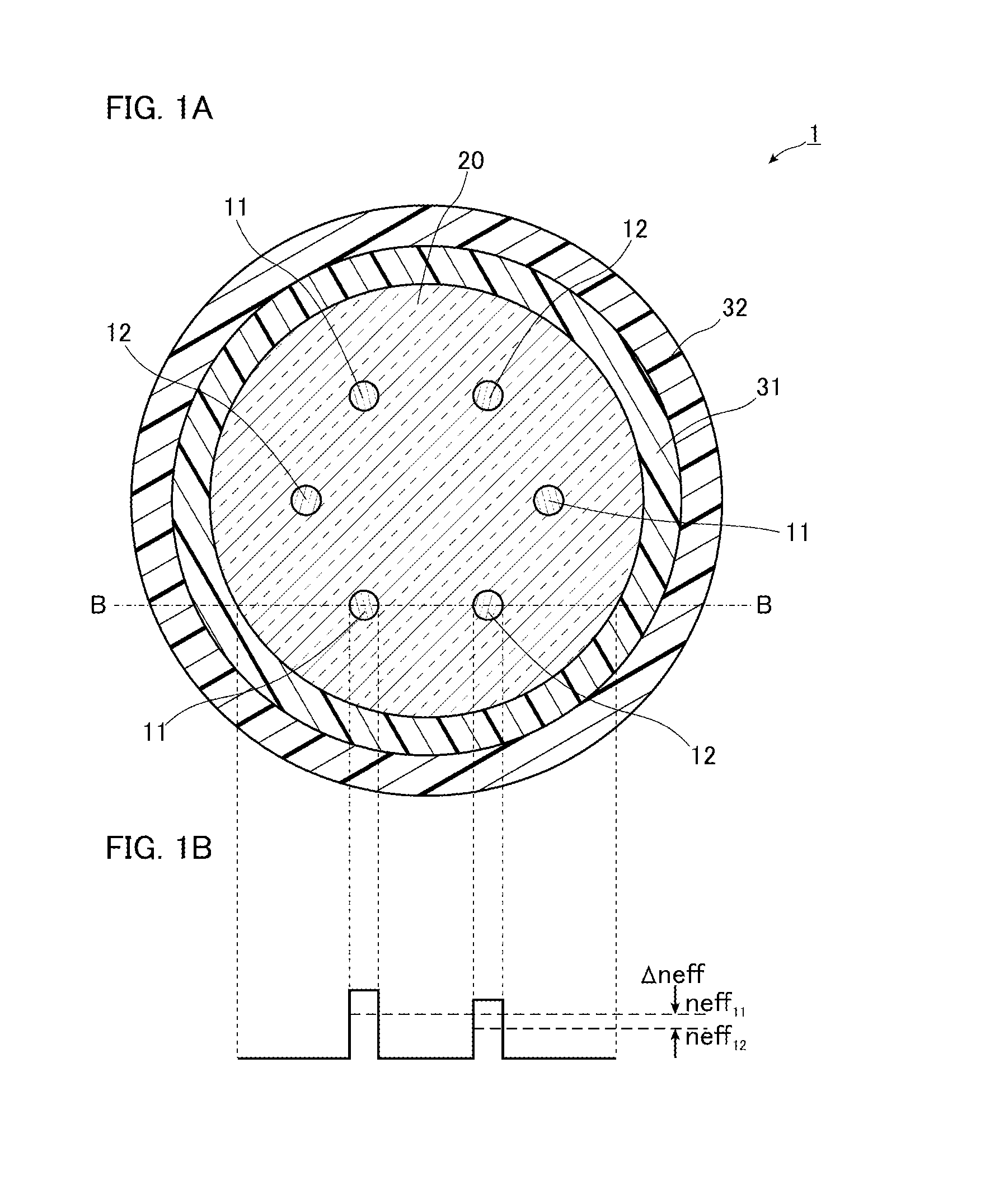
[0058]FIGS. 1A and 1B are diagrams of a multi-core fiber according to an embodiment of the present invention. More specifically, FIG. 1A is a diagram of a structure on a cross section perpendicular to the longitudinal direction of the multi-core fiber, and FIG. 1B is a schematic diagram of effective refractive indices along a line B-B of the multi-core fiber 1 in FIG. 1A. It is noted that FIG. 1B schematically depicts the effective refractive indices in the case where the multi-core fiber is disposed linearly.

[0059]As depicted in FIG. 1A, the multi-core fiber 1 according to the embodiment includes a plurality of two types of cores 11 and 12 whose effective refractive indices are different from each other, a clad 20 that surrounds the cores 11 and 12 entirely, fills the space between the cores 11 and 12, and surrounds the outer circumferential surface of the cores 11 and 12 with no spacing, an inner protective layer 31 that covers the outer circumferential surface of the clad 20, and...

second embodiment

[0086]Next, a second embodiment of the present invention will be described in detail with reference to FIGS. 7A and 7B. It is noted that components the same as or equivalent to the components of the first embodiment are designated the same reference numerals and signs, and the overlapping description is omitted unless otherwise specified.

[0087]FIGS. 7A and 7B are diagrams of a multi-core fiber according to the second embodiment of the present invention. More specifically, FIG. 7A is a diagram of a structure on a cross section perpendicular to the length direction of a multi-core fiber 2 according to the embodiment, and FIG. 7B is a schematic diagram of refractive index profiles and effective refractive indices along line B-B in FIG. 7A. Thus, the relationship between the refractive index and the effective refractive index does not always fall as in FIG. 7B.

[0088]As depicted in FIG. 7A, the multi-core fiber 2 according to the embodiment is different from the multi-core fiber 1 accord...

examples

[0105]Hereinafter, although the present invention will be more concretely explained with examples and comparative examples, the present invention is not limited thereto.


PUM


Abstract

A multi-core fiber includes an even number of six or more of cores and a clad that surrounds the outer circumferential surfaces of the cores. The cores are formed of two types of cores and in which an effective refractive index difference in a fundamental mode is 0.002 or less in a predetermined range or more that the effective refractive index difference in the fundamental mode is varied according to a core pitch. Two types of the cores are alternately and annularly disposed at regular spacings. A difference in the mode field diameter of light propagating through the cores is 1 μm or less.

Description

TECHNICAL FIELD[0001]The present invention relates to a multi-core fiber that can suppress the crosstalk between cores adjacent to each other even in the case where the multi-core fiber is nonlinearly disposed while suppressing splicing losses.BACKGROUND ART[0002]Currently, optical fibers used for optical fiber communication systems which are generally spreading adopt a structure in which an outer periphery of one core is surrounded by a clad, and information is transmitted when an optical signal propagates in this core. Further, as the optical fiber communication systems spread, the amount of information to be transmitted is dramatically increasing in recent years. Following an increase in the amount of information to be transmitted, the optical fiber communication systems use several tens or several hundreds of multiple optical fibers to perform long-distance optical communication of a large volume.[0003]It is known that, to reduce the number of optical fibers in such an optical f...

Claims


Application Information

Patent Timeline
IPC IPC(8): G02B6/02
CPCG02B6/02042
Inventor MATSUO, SHOICHIROSAITOH, KUNIMASAKOSHIBA, MASANORI
Owner THE FUJIKURA CABLE WORKS LTD
Why Eureka
Try Eureka