Bend insensitive single mode optic fiber with large effective area and manufacturing method thereof

A bending-insensitive, effective area technology, applied to multi-layer core/cladding optical fibers, cladding optical fibers, manufacturing tools, etc., can solve the problems of optical fiber mismatch, increased optical fiber connection loss, and high optical fiber manufacturing costs. The effect of low light loss

Active Publication Date: 2010-01-13
SHANTOU HIGH TECH ZONE AOXING OPTICAL COMM EQUIP
View PDF4 Cites 32 Cited by
  • Summary
  • Abstract
  • Description
  • Claims
  • Application Information

AI Technical Summary

Problems solved by technology

However, the mode field diameter of the optical fiber is quite different from that of the G.652 optical fiber, and the outer diameter of the glass part of the optical fiber is 80 μm, which is different from the 125 μm outer diameter of the conventional G.652 optical fiber. The problem of mismatching, resulting in an increase in the connection loss with the G.652 optical fiber
[0005] Studies have shown that the structural design of the air cladding can improve the bending resistance of the optical fiber. US Patent US6771865 describes an optical fiber with improved bending performance proposed by the applicant Corning, but the manufacturing cost of this type of optical fiber is relatively high. High, not conducive to promotion and use

Method used


Image

  • Bend insensitive single mode optic fiber with large effective area and manufacturing method thereof
  • Bend insensitive single mode optic fiber with large effective area and manufacturing method thereof
  • Bend insensitive single mode optic fiber with large effective area and manufacturing method thereof

Examples


Embodiment Construction

[0034] The present invention will be described in further detail below in conjunction with embodiment.

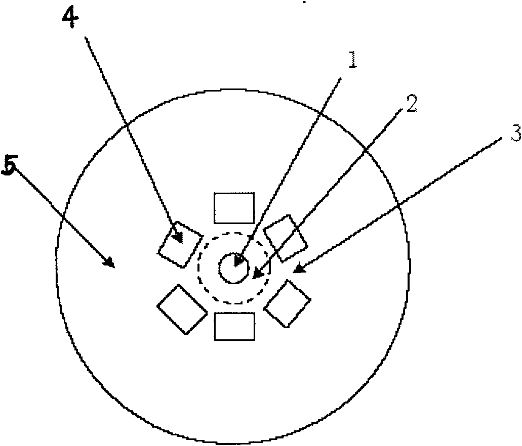
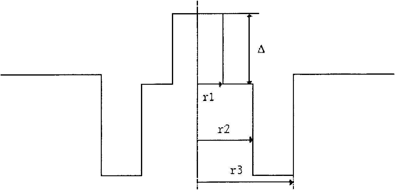
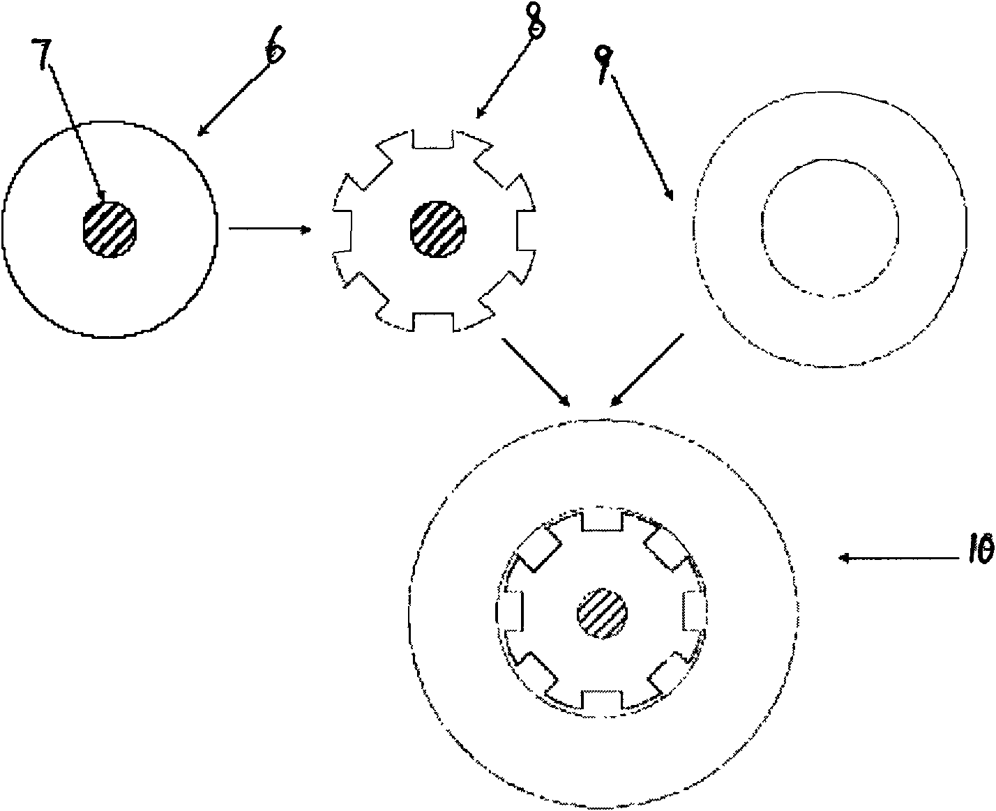
[0035] The G.652 low water peak optical fiber core rod is prepared by PCVD process, and the surface is opened in an approximate square along its axial direction (because the core rod is cylindrical, so the outer edge of the groove is arc-shaped,) the groove is grooved on the side. The central mandrel, the slots are uniformly distributed in the circumferential direction; after cleaning and drying, the RIC process is used to assemble the RIC process preform with the high-purity quartz tube. The main parameters of the preform are shown in Table 1; the RIC preform is directly drawn , using optical fiber coating materials for single-mode optical fiber production, the drawing speed is 800 m / min, the diameter of the optical fiber is 125±0.7μm, and the internal pressure of the RIC is controlled to be 800-950mbar. Analyze the end face of the optical fiber with a microscope to confir...


PUM

PropertyMeasurementUnit
radiusaaaaaaaaaa
diameteraaaaaaaaaa
refractive indexaaaaaaaaaa

Abstract

The invention relates to bend insensitive single mode optic fiber with a large effective area and a manufacturing method thereof. The bend insensitive single mode optic fiber with the duty ratio eta of the hole being 40 to 60 percent is obtained by wire drawing on a wire-drawer-tower through a prefabricated rod which is composed of a central core rod with uniform grooves on the side surface and a large casing pipe. Compared with conventional G.652 optic fiber, the cable cut-off wavelength of the optic fiber is less than or equal to 1260 nm, and the mode field diameter (MFD) is within 9.0 to 10.0 mu m. The optic fiber has 0.1 dB / circle and 0.2 dB / circle or even smaller bending supplementary loss respectively with the bending radii of 7.5 mm and 5.0 mm and at 1625 nm. Because the optic fiber has very low optical loss caused by bending, the optic fiber is particularly suitable for the operation of the optic fiber with small bending radii, such as the fiber to the home (FTTH) project or miniaturized optical devices.

Description

technical field [0001] The invention relates to a bending-insensitive single-mode optical fiber with a large effective area used in the field of optical fiber communication, especially in "fiber to the home" or miniaturized optical devices and a manufacturing method thereof. Background technique [0002] With the development of fiber-to-the-home (FTTH), the laying of optical fibers is getting closer to the terminal users. When considering the laying of optical fibers in homes and offices, the optical fiber is required to have different transmission characteristics from ordinary G.652 optical fibers, especially the optical fiber is required to have good bending resistance. Because the optical fiber will encounter a very small bending radius of 10mm, 7.5mm or even 5mm during the indoor laying process, the optical fiber must have the performance of very low additional loss in the case of an extremely small bending radius. In miniaturized optical devices, it is also required th...

Claims


Application Information

Patent Timeline
Patent Type & Authority Applications(China)
IPC IPC(8): G02B6/036C03B37/01C03B37/018C03B37/025
CPCC03B2203/14C03B37/02781C03B37/01211C03B37/01234
Inventor 杨晨韩庆荣罗杰
Owner SHANTOU HIGH TECH ZONE AOXING OPTICAL COMM EQUIP
Why Eureka
Try Eureka