
Method and system for performance management of an energy storage device

a technology of energy storage device and performance management, which is applied in the direction of secondary cell servicing/maintenance, automatic control ignition, instruments, etc., can solve the problems of energy storage device overheating, affecting the ability of storage device to continue providing services, and affecting the ability of service providers to provide services

Active Publication Date: 2014-11-13
FLUENCE ENERGY LLC
View PDF90 Cites 50 Cited by
  • Summary
  • Abstract
  • Description
  • Claims
  • Application Information

AI Technical Summary

Benefits of technology

The present patent is about a system and method for managing and maintaining the state of charge of an energy storage device by adjusting the response to grid operator commands to perform ancillary services. The system uses different algorithms to control the state of charge and temperature of the energy storage device while providing frequency regulation or intermittent renewable regulation services. The algorithms include a dynamic bias algorithm, a set point autopilot algorithm, a fixed signal bias algorithm, a signal bias range maintaining algorithm, an operational limits algorithm, and an intelligent algorithm selection system. The technical effects of the patent include improved control of energy storage devices in power pools and regions, better stability of the power grid, and better utilization of intermittent renewable resources.

Problems solved by technology

Failure to meet these MTRs may result in the service provider not being allowed to provide the service.
In the process of providing these services, the energy storage device can occasionally overheat, approach full, approach empty, or encounter some other condition that might impair the storage device's ability to continue providing services.
The problem is how to bias the response to the signal from the grid operator without violating the grid operator's MTRs so as to allow the energy storage device to get the highest performance score it is capable of achieving.

Method used


Image

  • Method and system for performance management of an energy storage device
  • Method and system for performance management of an energy storage device
  • Method and system for performance management of an energy storage device

Examples


Embodiment Construction

[0041]The present disclosure is directed to methods and systems for carrying out the following embodiments, which are described herein with reference to various algorithms, procedures, and technical solutions.

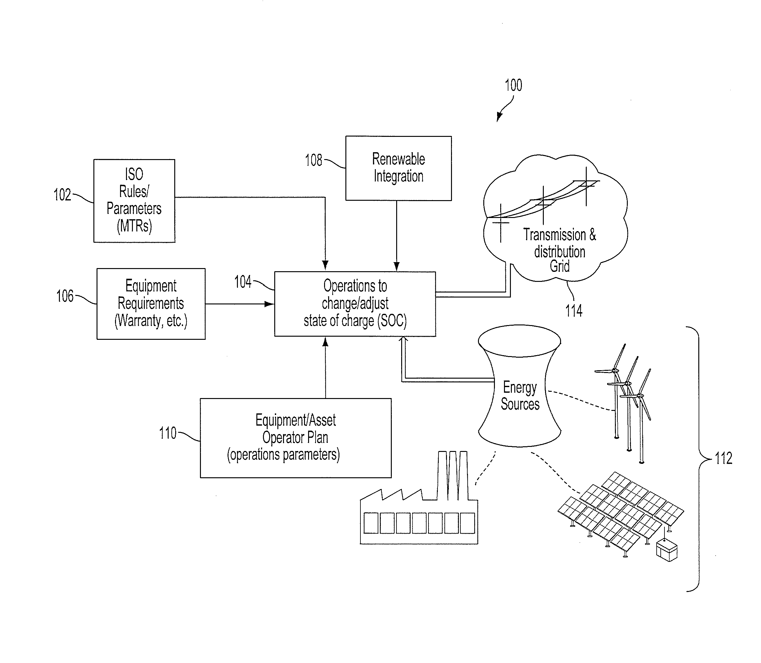
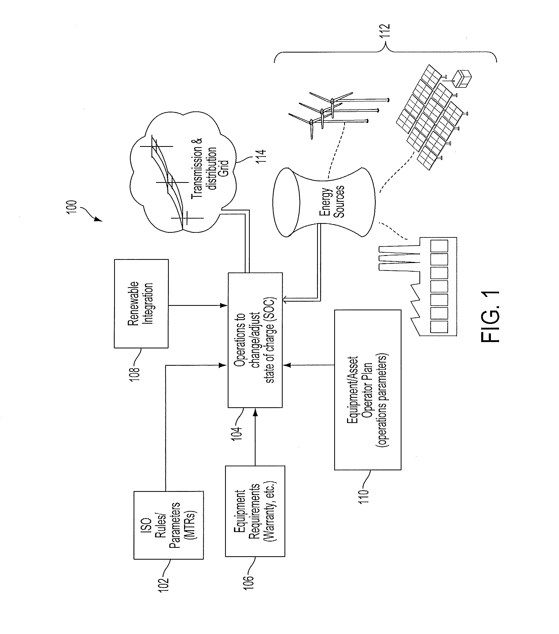
[0042]FIG. 1 depicts an exemplary operating environment 100 for energy sources 112 connected to an electric grid 114. As shown in FIG. 1, operations 104 to adjust a state of charge (SOC) for an energy storage device within the environment 100 can be based upon a plurality of parameters, rules, and inputs, including, but not limited to MTRs 102 of an operator of the grid 114, equipment requirements 106, renewable integration factors 108, and / or equipment operator parameters 110. In the non-limiting example shown in FIG. 1, the MTRs 102 are rules set by an ISO that operates a transmission and distribution (T&D) grid 114. In alternative embodiments, an RTO, a power pool, or other operator of the grid 114, such as an individual electric power utility, can establish the MTRs 102 acc...


PUM


Abstract

Approaches for managing and maintaining a state of charge of an energy storage device by adjusting (biasing) responses to electrical grid operator commands to perform ancillary services are disclosed. In embodiments, methods and systems regulate a set point regulation in an energy system. In an embodiment, a method determines when the set point needs to be changed, calculates a new set point, and moves the output of the system from an old set point to the new set point at a defined ramp rate. The method then incorporates, as part of a set point algorithm, the capability to restore the energy storage device to a desirable state of charge (SOC). Embodiments implement Dynamic Bias, SOC and Signal Bias Range Maintaining, Operational Limits, and Fixed Signal Bias algorithms and perform Intelligent Algorithm Selection to manage and maintain the SOC of an energy storage device by biasing responses to grid operator commands.

Description

CROSS-REFERENCE TO RELATED APPLICATIONS[0001]The present application claims the benefit of U.S. Provisional Appl. No. 61 / 569,020 entitled “Frequency Responsive Charge Sustaining Control of Electricity Storage Systems for Ancillary Services on an Electrical Power Grid,” filed Dec. 9, 2011 which is incorporated by reference herein in its entirety. The present disclosure describes modifications to the operation of power plants and energy services in electrical power grid systems. Examples of such power plants, energy services, and electrical power grids are described in U.S. application Ser. No. 12 / 248,106 entitled “Frequency Responsive Charge Sustaining Control Of Electricity Storage Systems For Ancillary Services On An Electrical Power Grid,” now U.S. Pat. No. 7,839,027, U.S. application Ser. No. 12 / 722,271 entitled “Regulation of Contribution of Secondary Energy Sources to Power Grid,” filed Mar. 11, 2010, and U.S. application Ser. No. 13 / 527,290 entitled “Hybrid Electric Generating...

Claims


Application Information

Patent Timeline
IPC IPC(8): H02J3/28G05B11/00
CPCH02J3/28G05B11/00H01M10/44H02J3/32H02J11/00H02J2300/20H02J3/381Y02E60/10H02J3/46Y02E70/30H02J3/38
Inventor GEINZER, JAY CRAIGSHELTON, JOHN CHRISTOPHERGALURA, BRETT LANCE
Owner FLUENCE ENERGY LLC
Learn More