Eureka AIR delivers breakthrough ideas for toughest innovation challenges, trusted by R&D personnel around the world.

Integrated gesture sensor module

a gesture sensor and integrated technology, applied in the field of gesture sensor modules, can solve the problems of light pollution or cross-talk, and reduce the assembly performance,

Active Publication Date: 2014-11-20
ANALOG DEVICES INC
View PDF11 Cites 27 Cited by
  • Summary
  • Abstract
  • Description
  • Claims
  • Application Information

AI Technical Summary

Benefits of technology

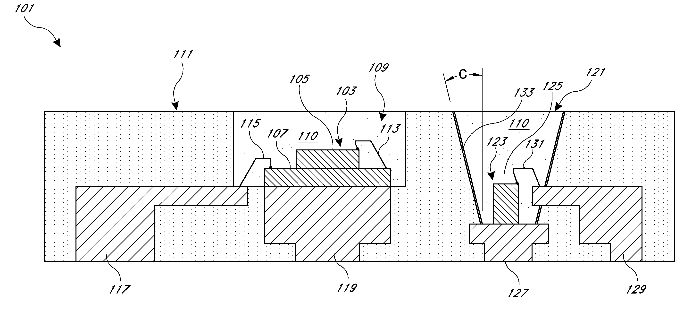
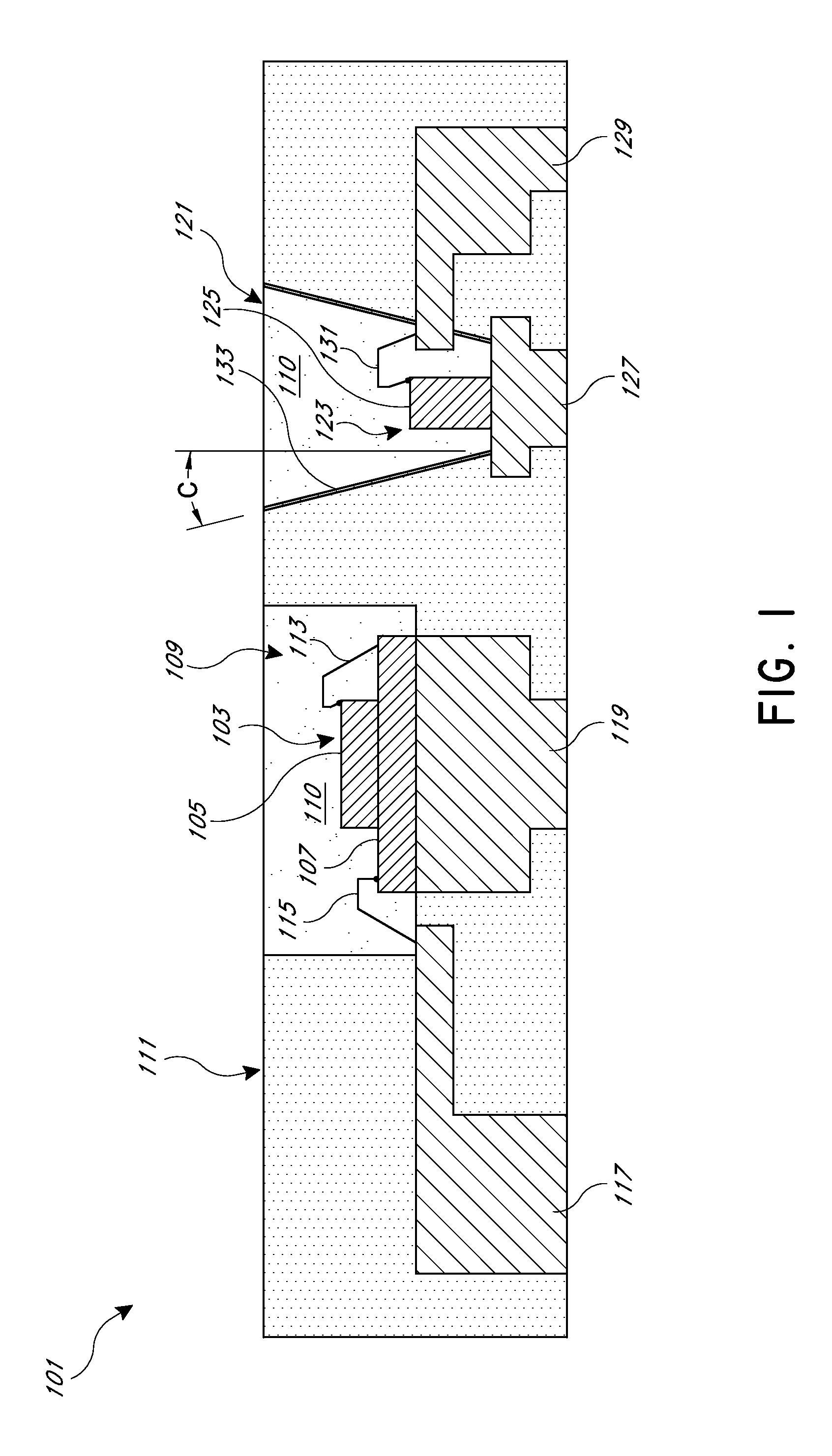
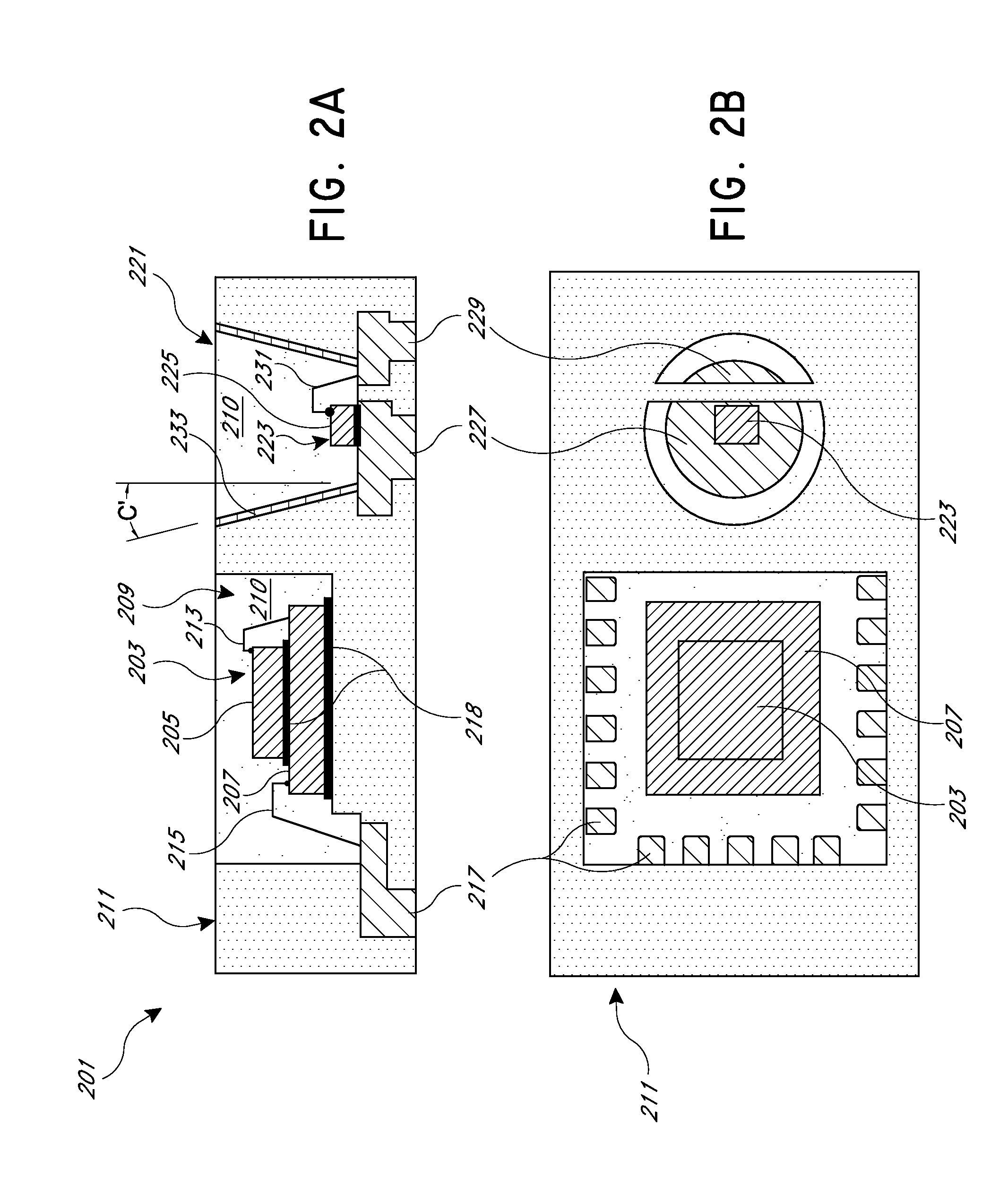
The patent describes a gesture sensor module that includes an optical emitter die and an optical sensor die placed in separate cavities within a package. The package includes an optical barrier to prevent light emitted from the emitter die from being reflected back to the sensor surface. The sensor surface is higher than the emitter surface, and the package can be integrated into larger electronic devices such as mobile computing devices or electronic touch screens. The method of manufacturing the module involves arranging the optical sensor die and the optical emitter die in the package, and disposing an optical barrier between the cavities. The technical effects of this invention include improved accuracy and reliability of gesture sensing, reduced interference between the emitter and sensor surfaces, and improved integration with other electronic components.

Problems solved by technology

In such arrangements, however, there may be risk of light pollution or cross-talk, in which some light from the optical emitter is detected by the adjacent optical sensor before being reflected by a user's hand prematurely.
Such cross-talk can decrease the performance of the assembly.

Method used


Image

  • Integrated gesture sensor module
  • Integrated gesture sensor module
  • Integrated gesture sensor module

Examples


Embodiment Construction

[0023]The following detail description of certain embodiments presents various descriptions of specific embodiments of the invention. However, the invention can be embodied in myriad different ways as defined and covered by the claims. In this description, reference is made to the drawings in which like reference numerals indicate identical or functionally similar elements.

[0024]As used herein, directional terms such as “over,”“under,”“above,”“below,”“top,”“bottom,” etc. are intended to indicate relative positioning of the identified components. Such terms are not intended to reference absolute positioning. Accordingly, the entire system can be oriented in any direction, either during manufacturing or in use. The description and claims may refer to elements or features as being “mounted” or “attached” together. As used herein, unless expressly stated otherwise, “mounted” means that one element / feature is directly or indirectly connected to another element / feature. Likewise, unless e...


PUM

PropertyMeasurementUnit
Lengthaaaaaaaaaa
Lengthaaaaaaaaaa
Lengthaaaaaaaaaa

Abstract

An integrated gesture sensor module includes an optical sensor die, an application-specific integrated circuit (ASIC) die, and an optical emitter die disposed in a single package. The optical sensor die and ASIC die can be disposed in a first cavity of the package, and the optical emitter die can be disposed in a second cavity of the package. The second cavity can be conical or step-shaped so that the opening defining the cavity increases with distance from the upper surface of the optical emitter die. The upper surface of the optical emitter die may be higher than the upper surface of the optical sensor die. An optical barrier positioned between the first and second cavities can include a portion of a pre-molded, laminate, or ceramic package, molding compound, and / or metallized vias.

Description

INCORPORATION BY REFERENCE TO ANY PRIORITY APPLICATIONS [0001]Any and all applications for which a foreign or domestic priority claim is identified in the Application Data Sheet as filed with the present application are hereby incorporated by reference under 37 CFR 1.57.BACKGROUND [0002]1. Field[0003]This invention relates to gesture sensor modules, and packaging therefor.[0004]2. Description of the Related Art[0005]Gesture sensors may be used to detect movement of an object, for example a user's hand. Such detection can be processed, for example, allowing a user to provide input to an electronic device by making certain gestures. Gesture sensors can be used in a wide variety of fields such as consumer electronics, healthcare, or telecommunications. Components for gesture sensing can include an optical emitter, an optical sensor die, and an associated application-specific integrated circuit (ASIC). The ASIC may be configured to process the output signal from the optical sensor die.[...

Claims


Application Information

Patent Timeline
IPC IPC(8): G06F3/042G06F3/01
CPCG06F3/017G06F3/042H01L2224/48095H01L2224/48145H01L2224/48465H01L2224/73265Y10T29/49826H01L2924/00012
Inventor SENGUPTA, DIPAKDELIWALA, SHRENIKZHAO, YINGFRIED, BRUCESCHOPPEE, WILLIAMBECKFORD, WOODROW
Owner ANALOG DEVICES INC
Why Eureka
Eureka Blog
Learn More