Method for producing high surface area foil electrodes

a foil electrode and high surface area technology, applied in the direction of fixed capacitors, metallic material coating processes, synthetic resin layered products, etc., can solve the problems of mechanical weakening of foils, difficult to fabricate electrolytic capacitors by high speed winding, and additional cost of working with two metals

Inactive Publication Date: 2001-12-13
ACKTAR
View PDF2 Cites 43 Cited by
  • Summary
  • Abstract
  • Description
  • Claims
  • Application Information

AI Technical Summary

Benefits of technology

[0028] The valve metal surface thus formed has a fractal-like structure, with a fractal dimension greater than 2. The scope of the present invention includes articles of manufacture in general, not just foil electrodes, that have valve metal surfaces or interfaces with such fractal-like surficial structures. This surficial structure may be on the surface of the article of manufacture, as in the case of a foil cathode of the present invention. Such a cathode has a higher capacitance than prior art cathodes of similar bulk composition and overall dimensions. Alternatively, the surficial structure may be an interface in the interior of the article of manufacture, as in the case of a foil anode, either a foil anode of the present invention or a foil anode formed by conventional anodization of a foil cathode of the present invention. In such an anode, the fractal-like valve metal surficial structure is covered by an oxide dielectric. In foil anodes of the present invention, the fractal-like surface structure allows the deposition of relatively thick dielectric layers while preserving the high surface area of the metal surface.
[0029] Because the present invention increases the surface area of a valve metal foil by adding material, rather than by removing material, as in conventional etching, the present invention allows the use of thinner foils in applications such as electrodes for electrolytic capacitors.

Problems solved by technology

In the case of very thin foils, this has the disadvantage of weakening the foils mechanically, making it difficult to fabricate electrolytic capacitors by high speed winding.
The disadvantages of this method of increasing the surface are of a foil electrode include the additional cost of working with two metals and the decrease in stability associated with an intermetallic potential.
Drake's foil has been found to be too brittle for use in electrolytic capacitors: it breaks when it is rolled into a cylindrical roll, the standard shape of an electrolytic capacitor.
Such mixed Al--Al.sub.2O.sub.3 surfaces are more robust mechanically than pure aluminum surfaces; but electrolytic capacitors incorporating them are known to have relatively high resistive losses and relatively low stability over time.
In addition, the presence of both aluminum and large quantities of aluminum oxide in the surface of the foil makes difficult and less effective both stabilization by subsequent conventional chemical or electrochemical treatments and structure coarsening by subsequent annealing.
For high voltage (upwards of 100 V) applications, the dielectric layer is relatively thick, and tends to bridge over fine surface features, reducing the effective surface area of the anode.
Two other phenomena tend to reduce the effective surface areas of anodes made by electrolytic anodization.

Method used


Image

  • Method for producing high surface area foil electrodes
  • Method for producing high surface area foil electrodes
  • Method for producing high surface area foil electrodes

Examples


example 2

Deposition of Discontinuous Aluminum Oxide Layer

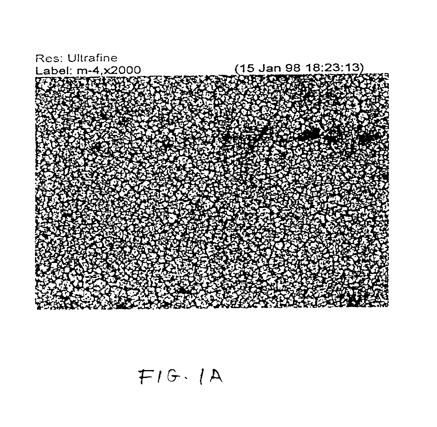
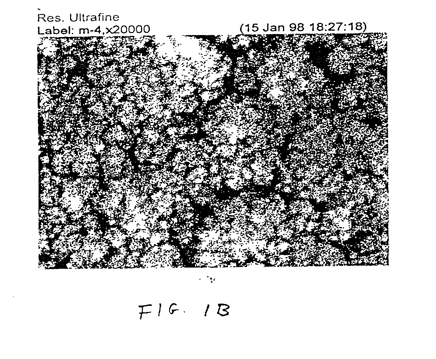
[0058] Aluminum foils with fractal-like surfaces were prepared as in Example 1, except that the foils were heated as described above during the evaporation of the aluminum to promote the formation of coarser surface structures. On each foil, a discontinuous layer of aluminum oxide, 500 .ANG. to 2000 .ANG. thick, was deposited by thermal resistive evaporation of aluminum in a pure oxygen atmosphere, at oxygen pressures of between 0.0015 torr and 0.007 torr. This deposition was effected in the same chamber as that in which the foil was prepared, to avoid uncontrolled oxidation in ambient air. Layer thicknesses were measured as described by Mattox on page 569. Simple electrical resistance measurements transverse to the foils using dry probe electrodes showed that the foils had negligible resistance to the transverse flow of electricity (short circuit), showing that the aluminum oxide layers were indeed discontinuous. By contrast, a foil o...


PUM

PropertyMeasurementUnit
voltageaaaaaaaaaa
pressureaaaaaaaaaa
pressureaaaaaaaaaa

Abstract

A method for increasing the surface area of foil electrodes of electrolytic capacitors. A valve metal is deposited by evaporation on a valve metal foil in a low pressure inert atmosphere including oxygen at a pressure one to two orders of magnitude lower than the pressure of the inert gas. The resulting surface is fractal-like. The foil thus treated is suitable as such for use as a cathode. Prior to anodization to produce an anode, a discontinuous layer of a valve metal oxide is deposited on the foil, to preserve the high surface area of the fractal-like surface and otherwise promote the formation of a dielectric coating whose interface with the metal foil has a high surface area.

Description

FIELD AND BACKGROUND OF THE INVENTION[0001] The present invention relates to electrodes for electrolytic capacitors and, more particularly, to a method for producing such electrodes, particularly anodes but also cathodes, having increased surface area, and the electrodes so produced.[0002] An electrolytic capacitor is a capacitor in which one plate is metallic and the other plate is an electrolyte. Intervening between the two plates is a dielectric consisting of a surface oxide coating on the metal plate. Conventionally, the metal plate on which the dielectric coating is formed is referred to as the anode. The term "anode" is used herein to refer both to the metal plate itself and to the combination of the metal plate with the dielectric coating. It will be clear from the context which meaning of "anode" is intended. A transition between ionic conduction in the electrolyte and electronic conduction in an external circuit is provided by a second metal plate which is referred to herei...

Claims


Application Information

Patent Timeline
Patent Type & Authority Applications(United States)
IPC IPC(8): C22F1/00C22F1/04C23C14/08C23C14/58H01G9/04H01G9/042H01G9/048H01G9/055H01L21/02
CPCC23C14/081C23C14/5806C23C14/5853H01G9/042Y10T29/43H01L28/84Y10T428/24926Y10T29/435Y10T29/417H01G9/048
Inventor KATSIR, DINATARTAKOVSKY, IRISTARTAKOVSKY, ISRAEL
Owner ACKTAR
Why Eureka
Try Eureka