Electronically dimmable optical device

a technology of optical devices and reflectors, which is applied in the direction of instruments, polarising elements, vehicle components, etc., can solve the problems of only aggravated, insufficient intensity of reflected headlights from trailing vehicles, and temporarily visual impair or dazzle the operator, so as to achieve the effect of varying the reflectivity of the device and the level of the devi

Active Publication Date: 2014-11-20
ALPHAMICRON INC
View PDF6 Cites 98 Cited by
  • Summary
  • Abstract
  • Description
  • Claims
  • Application Information

AI Technical Summary

Benefits of technology

[0033]In some example, the method includes: setting the active polarizer to be in a non-absorptive state when not energized, and to absorb an x-direction polarization of incident light and transmit a y-direction polarization when energized by application of a voltage; setting the first reflective polarizer to reflect the same x-direction polarization that the active polarizer absorbs; setting the second reflective polarizer to reflect the orthogonally opposite y-direction polarization of light; and setting the active polarization rotator to have no effect when non-energized and to rotate the polarization direction of light by up to 90° when energized by a maximum voltage. The level of reflectivity of the device can be varied by applying a variable volta...

Problems solved by technology

Bright lights appearing in a scene behind the vehicle, such as from another vehicle approaching from the rear, may create glare in a rearview mirror that can temporarily visually impair or dazzle the operator.
This problem is only aggravated under low ambient light conditions such as at night, when the eyes of the driver have adjusted to the darkness.
With the low intensity of light reflected to the driver, the intensity of reflected headlights from trailing vehicles is insufficient to impair the driver's vision.
Difficulties with manually controlled mirrors include the glare experienced before the mirror could be switched, as well as driver distraction caused by finding and operating the switch lever.
However, electrochromic mirrors suffer from many limitations such as slow response rate, high temperature sensitivity, and high power consumption.
However, liquid crystal based systems typically use static (not switchable) absorptive polarizers for light attenuation, which often reduces the reflectivity to <50% or <40%, even in the highly reflective state.
However, these systems still do not offer the high reflectance or wide swing...

Method used


Image

  • Electronically dimmable optical device
  • Electronically dimmable optical device
  • Electronically dimmable optical device

Examples


example 1

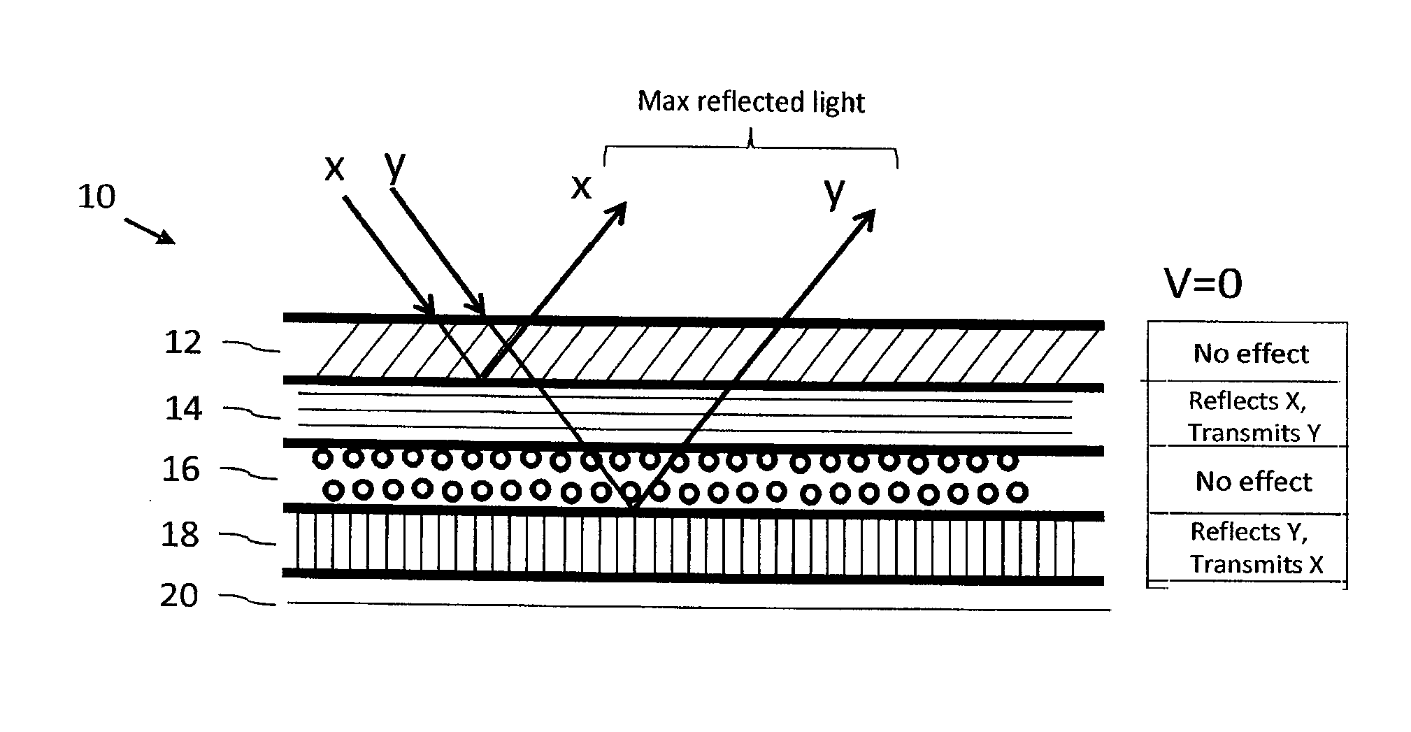
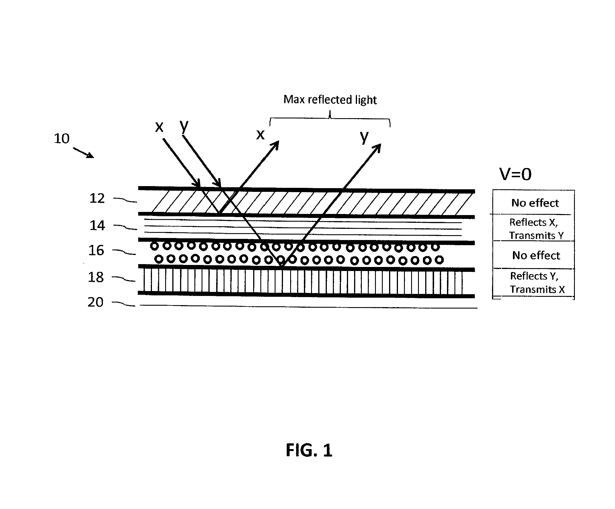
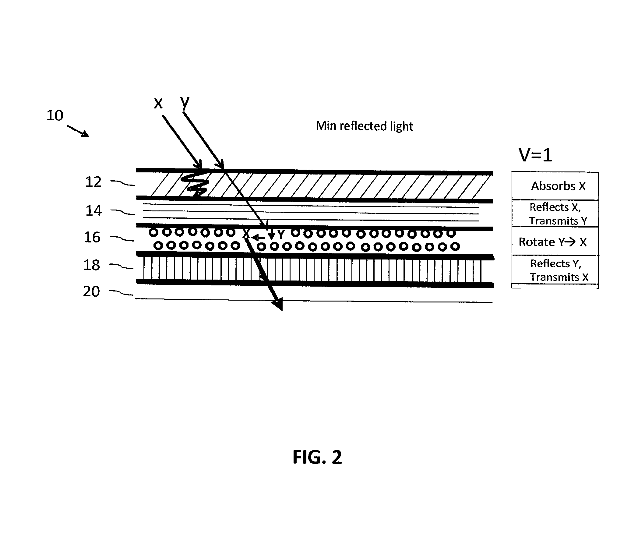
[0095]FIGS. 1 and 2 show a first configuration assembly 10, which is designed for a dimming system and comprises of the following layers: an active polarizer 12 with an absorptive axis in the x-direction (when activated) at the viewing surface 13 of the device, adjacent a static reflective polarizer 14 with a reflective axis in the x-direction, adjacent an active polarization rotator 16, adjacent a static reflective polarizer 18 with a reflective axis in the y-direction. It should be noted that the active polarizer and the active polarization rotator may be independently operated.

[0096]FIG. 1 and Table 1 show the device functioning in an OFF (V=0 or voltage-off) state. Unpolarized light 30 with both x and y polarizations is incident on the first active absorptive polarizer 12 oriented in the x-direction. With no voltage applied, the active absorptive polarizer 12 will have minimal effect on the incident polarizations. Therefore, both polarizations will predominantly pass through to ...

example 2

[0102]In another embodiment, shown in FIGS. 3 and 4, a second configuration designed for a dimming system is shown. The system 50 includes: an active polarizer 52 with absorptive axis in the x-direction when activated, adjacent a first static reflective polarizer 54 with a reflective axis in the x-direction, adjacent an active polarization rotator 56, followed by a second static reflective polarizer 58 with reflective axis in the x-direction. It should be noted that the active polarizer 52 and the active polarization rotator 56 may be independently operated.

[0103]FIG. 3 and Table 3 show the device functioning in an OFF (v-0 or the voltage off) state. Unpolarized light 30 with both x and y polarization is incident on the first (active absorptive polarizer) oriented in the x-direction. With no voltage applied, the active absorptive polarizer 52 will have minimal effect on the incident polarizations. Therefore, both polarizations will predominantly pass through to the next surface. The...

example 3

[0108]FIG. 5 shows a configuration of a mirror device corresponding to the that shown in Example 1 but with the addition of a display device on the non-viewing side of the mirror.

[0109]FIG. 5 shows how when a maximum voltage is applied (Vmax), the x-direction polarized light emitted from the display device 100 will be transmitted through the second static reflective polarizer 18 to the polarization rotator 16, which will rotate the polarization direction of the light to a y-direction. This y-direction light will then pass through the first static reflective polarizer 14 and the active polarizer 12 largely unaffected, to emerge through to the viewing surface 13 of the mirror 10.

[0110]In this configuration, the display light has the same polarization as the polarization axis of the absorptive polarizer.


PUM


Abstract

An electronically dimmable optical device, including, in sequence, an active absorbing polarizer; a first static reflective polarizer; an active polarization rotator; and a second static reflective polarizer; configured so that the reflectivity and/or transmissivity of the device can be controlled (increased or decreased) by application of a voltage across the active absorbing polarizer and/or the active polarization rotator. One or more polarization levels can be selected by controlling the voltage at the active absorptive polarizer such that setting the active absorptive polarizer to a selected polarization level determines the brightness of an image produced by the device.

Description

CROSS-REFERENCE TO RELATED APPLICATION[0001]This application claims priority to, and any other benefit of, U.S. Provisional Patent Application Ser. No. 61 / 592,883 entitled ELECTRONICALLY DIMMABLE MIRROR and filed Jan. 31, 2012, the entire disclosure of which is fully incorporated herein by reference.TECHNICAL FIELD[0002]The present invention relates to electronically dimmable reflective or transmissive optical devices using various reflective polarizer, absorptive polarizer and polarizer rotator configurations for use in vehicles, windows, visors, helmets, mobile phones and various other applications.BACKGROUND ART[0003]In vehicles, drivers generally use an interior rearview mirror and two exterior side view mirrors (hereinafter referred to collectively as “rearview mirrors”). The rearview mirrors allow the driver to view scenes behind the vehicle without having to face in a rearward direction and to view areas around the vehicle that would otherwise be blocked by the vehicle struct...

Claims


Application Information

Patent Timeline
IPC IPC(8): G02F1/01B60R1/08G02B5/30
CPCG02F1/0136B60R1/088G02B5/3025G02B27/281G02F1/133528G02F1/133536G02F1/13475G02F2203/01G02F2203/02G02F2203/62G02F1/133531G02F1/133638
Inventor TAHERI, BAHMAN
Owner ALPHAMICRON INC
Why Eureka
Try Eureka