Light intensity distribution conversion element, planar light source device, and liquid crystal display device
a technology of light intensity distribution and conversion element, which is applied in the direction of lighting and heating apparatus, semiconductor devices for light sources, instruments, etc., can solve the problems of low color purity, narrow color reproduction range in liquid crystal display devices, and low color purity of light emitted from ccfls and leds, etc., to achieve excellent uniformity, wide color reproduction range, and simplified configuration
- Summary
- Abstract
- Description
- Claims
- Application Information
AI Technical Summary
Benefits of technology
Problems solved by technology
Method used
Image

Examples
embodiment 1
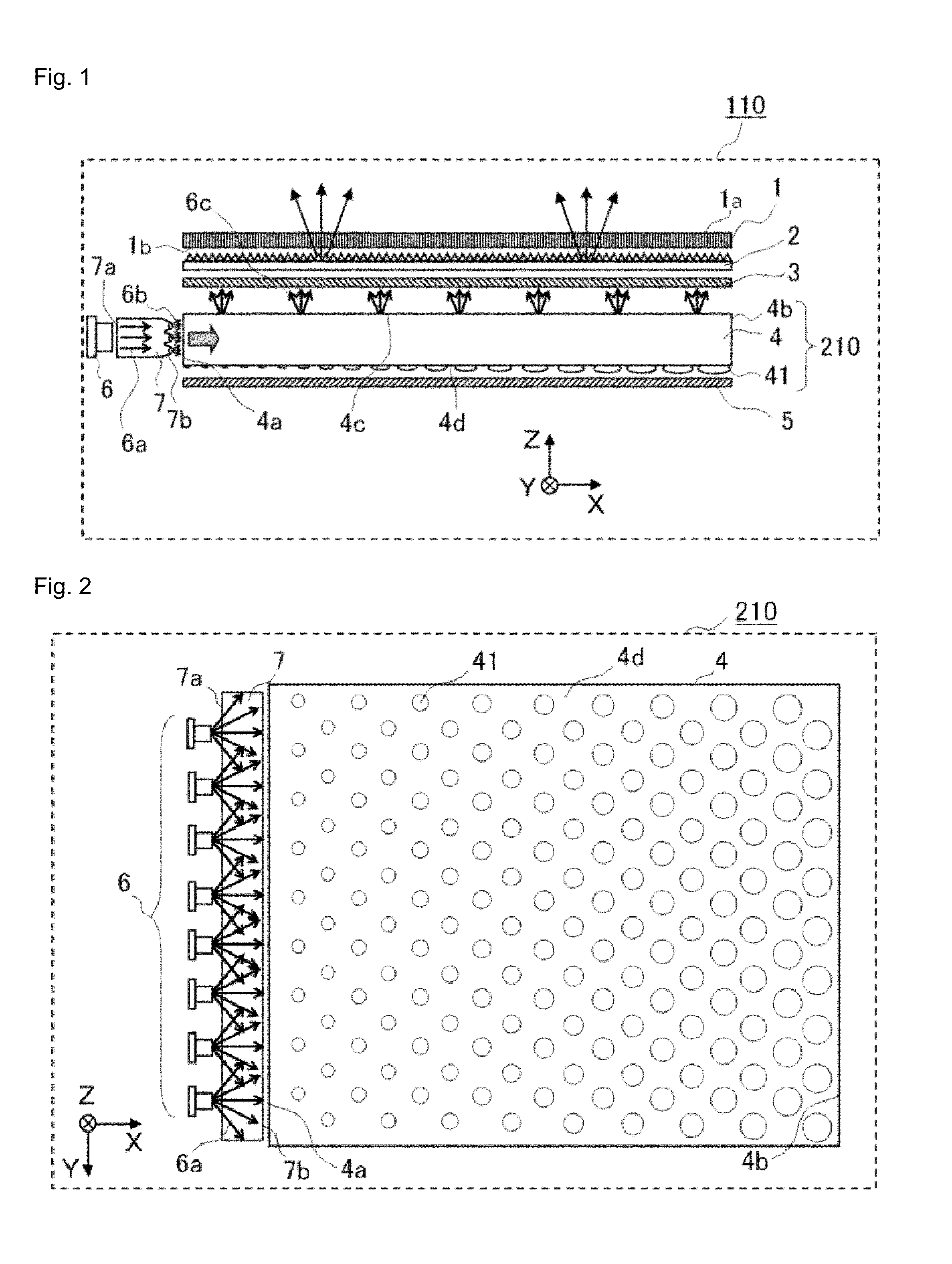
[0033]FIG. 1 is a diagram schematically showing a configuration of a liquid crystal display device 110 which is a transmission type display device according to Embodiment 1 of the present invention. In order to facilitate the explanation of FIG. 1, the short side direction of a liquid crystal optical element 1 is set to be the Y axis direction, the long side direction thereof is set to be the X axis direction, the direction normal to the X-Y plane is set to be the Z axis direction, and the display surface 1a side of the liquid crystal display element 1 is set to be the +Z axis direction. The upper direction of the liquid crystal display device is set to be the +Y axis direction, and the light emitting direction of a first light source 6 described later is set to be the +X axis direction. In the following drawings, the left hand side of the liquid crystal display device when viewed from its front side is the +X axis direction.
[0034]As shown in FIG. 1, the liquid crystal display devic...
embodiment 2
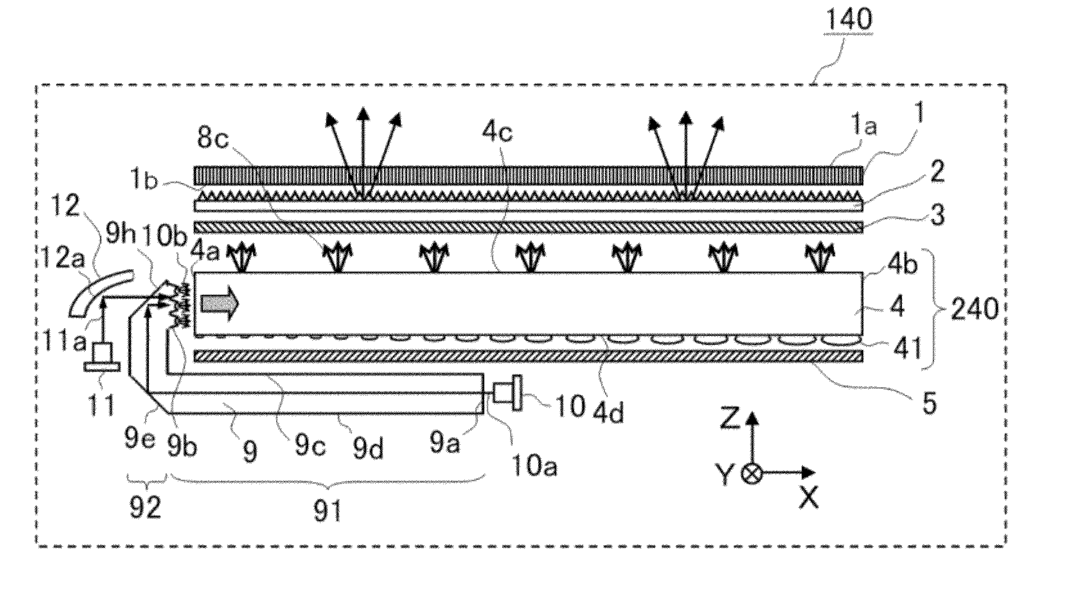
[0085]FIG. 12 is a diagram schematically showing a configuration of a liquid crystal display device 120 which is a transmission type display device according to Embodiment 2 of the present invention. The liquid crystal display device 120 in Embodiment 2 is the same, except that a planar light source device 220 is different from the planar light source device 210, with the liquid crystal display device 110 in Embodiment 1. That is, the liquid crystal optical element 1, the optical sheets 2 and 3, and the light reflection sheet 5 are the same with those in the liquid crystal display device 110 in Embodiment 1. Configuring elements similar to those explained in the liquid crystal display device 110 in Embodiment 1 are indicated by the same reference numerals, and the detailed explanation thereof will be skipped.
[0086]The planar light source device 220 in Embodiment 2 has a light source 8, a light intensity distribution conversion element 9, and the light guide plate 4. The light guide ...
embodiment 3
[0099]FIG. 16 is a diagram schematically showing a configuration of a liquid crystal display device 130 which is a transmission type display device according to Embodiment 3 of the present invention. FIG. 17 is a configuration diagram showing a planar light source device 230 when viewed from the −Z axis direction. In the liquid crystal display device 130 in Embodiment 3, the planar light source device 230 is different from the planar light source device 220 in Embodiment 2 in a manner that a first light source 10 is disposed instead of the light source 8 and a second light source 11 is further disposed. That is, the liquid crystal optical element 1, the optical sheets 2 and 3, the light guide plate 4, the light reflection sheet 5, and the light intensity distribution conversion element 9 are the same with those in the liquid crystal display device 120 in Embodiment 2. The same will apply to the configuring elements in the liquid crystal display device 120 in Embodiment 2 which are t...
PUM
 Abstract
Description
Claims
Application Information
 - R&D
- Intellectual Property
- Life Sciences
- Materials
- Tech Scout
- Unparalleled Data Quality
- Higher Quality Content
- 60% Fewer Hallucinations
Browse by: Latest US Patents, China's latest patents, Technical Efficacy Thesaurus, Application Domain, Technology Topic, Popular Technical Reports.
© 2025 PatSnap. All rights reserved.Legal|Privacy policy|Modern Slavery Act Transparency Statement|Sitemap|About US| Contact US: help@patsnap.com