
Oil-retaining bearing and fixing structure thereof

Inactive Publication Date: 2014-11-20
ASIA VITAL COMPONENTS SHENZHEN CO LTD
View PDF6 Cites 0 Cited by
  • Summary
  • Abstract
  • Description
  • Claims
  • Application Information

AI Technical Summary

Benefits of technology

The present invention provides an oil-retaining bearing and a fixing structure that can improve the support of the bearing, reduce friction, and minimize noise. It also increases the amount of lubricant retained in the bearing and maintains lubrication between the bearing and the shaft.

Problems solved by technology

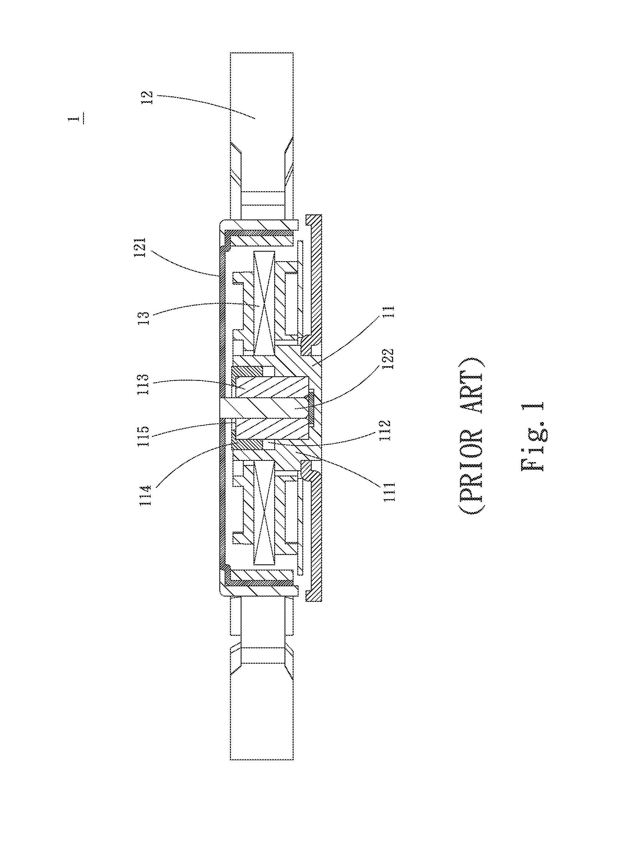
In the case that the heat is not dissipated in time, the temperature of the CPU will rise to cause deterioration of the execution performance of the CPU.
When the heat accumulates to an extent higher than the tolerance limit, the computer will crash or even burn out.
Therefore, it has become a critical issue how to quickly dissipate the heat generated by the CPU and other heat generation components.
On the other hand, an ordinary large-scale electronic device such as a working station or a server will generate high heat in operation.
When the operation temperature exceeds a certain working temperature, the working performance of the working station or server will be affected at high temperature.
In some more serious cases, the electronic components in the working station or server may burn out to cause malfunction.
The temporary crush or burnout of the working station or server will lead to great loss, especially in the case that many databases or files are stored in the working station or server.
As a result, when the shaft rod rotates within the bearing, the shaft rod tends to shake to make noise.
1. The support force between the shaft rod and the bearing is reduced.
2. When the shaft rod rotates within the bearing, the shaft rod tends to shake to make noise.
3. The amount of the lubricant retained in the bearing is decreased and the lubrication is reduced.

Method used


Image

  • Oil-retaining bearing and fixing structure thereof
  • Oil-retaining bearing and fixing structure thereof
  • Oil-retaining bearing and fixing structure thereof

Examples


Embodiment Construction

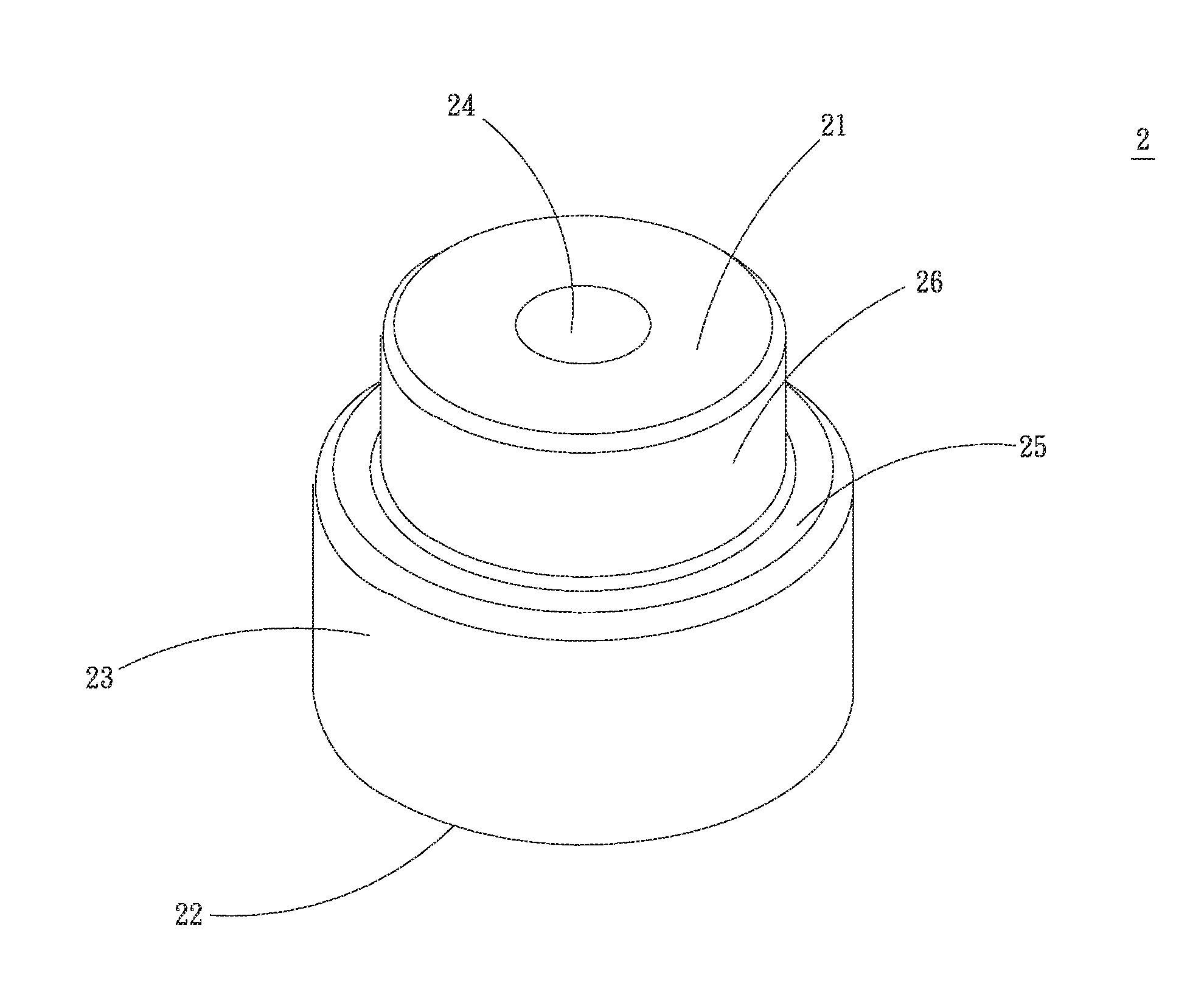
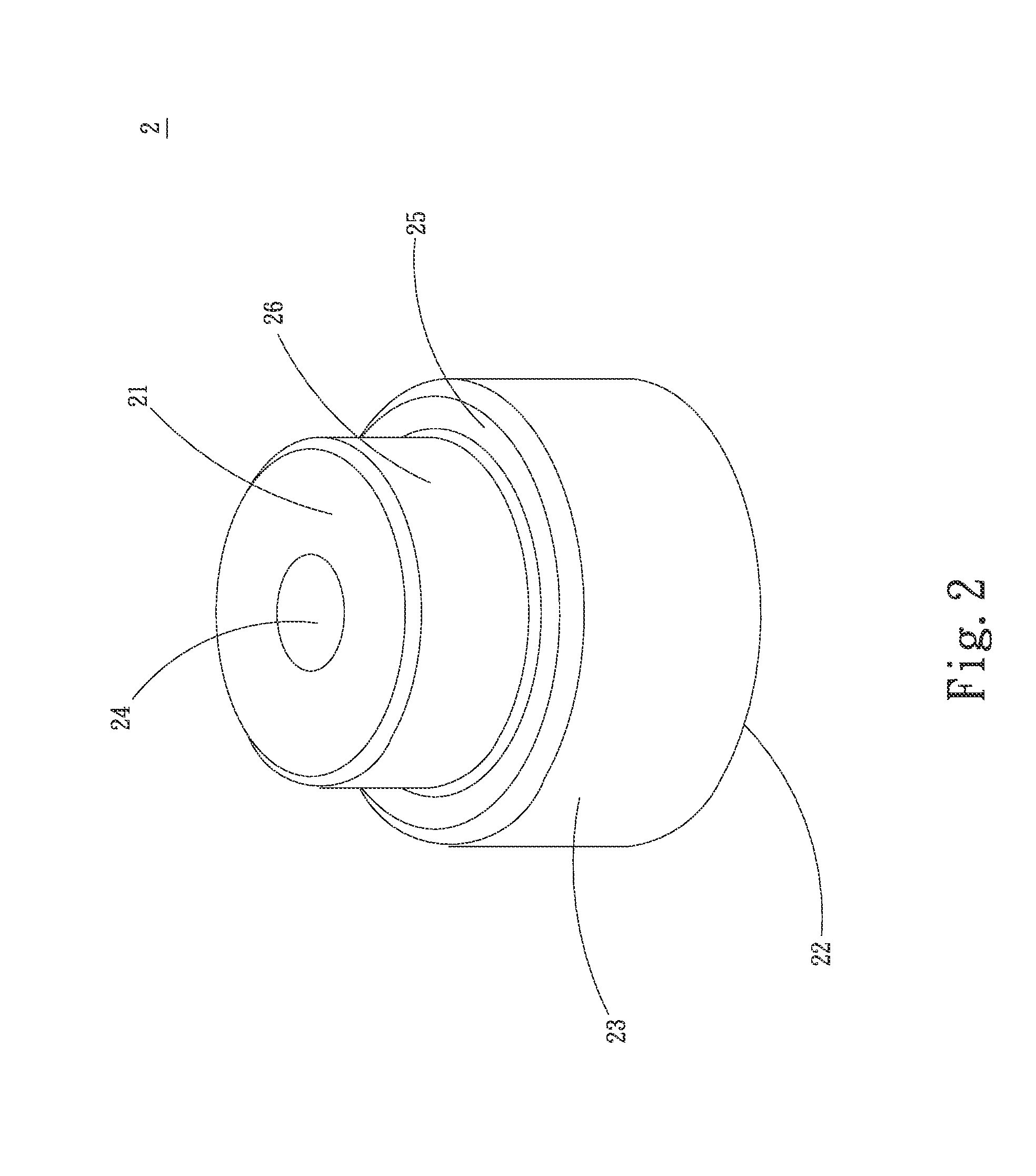
[0029]Please refer to FIG. 2, which is a perspective assembled view of a first embodiment of the oil-retaining bearing of the present invention. The oil-retaining bearing includes a bearing main body 2 having a top section 21 and a bottom section 22. The bearing main body 2 has an outer circumference 23 and a small-diameter abutment section 26, which are formed between the top section 21 and the bottom section 22. A stepped rest section 25 is defined between the outer circumference 23 and the abutment section 26. The abutment section 26 is positioned between the rest section 25 and the top section 21. A shaft hole 24 is formed at a center of the bearing main body 2 between the top section 21 and the bottom section 22. The width of the rest section 25 is smaller than the width of the bottom section 22. The length of the abutment section 26 is shorter than the length of the shaft hole 24.

[0030]Please now refer to FIGS. 3 and 4A. FIG. 3 is a sectional exploded view of a first embodimen...


PUM


Abstract

An oil-retaining bearing and a fixing structure thereof. The fixing structure includes: a base seat having a bearing cup formed with a bearing hole; a bearing main body disposed in the bearing hole, the bearing main body having an outer circumference and a shaft hole formed between a top section and a bottom section, the bearing main body being further formed with a stepped rest section between the outer circumference and the top section; and a fixing member formed with a fixing section and a restriction section. The fixing section is disposed in the bearing cup in abutment with the rest section. The restriction section is positioned at the top end of the bearing cup. The fixing section is positioned between the bearing main body and the bearing cup to fix the bearing main body, whereby the support of the bearing main body is enhanced to reduce the friction.

Description

BACKGROUND OF THE INVENTION[0001]1. Field of the Invention[0002]The present invention relates generally to an oil-retaining bearing, and more particularly to an oil-retaining bearing and a fixing structure thereof, which can enhance the support of the bearing main body so as to reduce the friction and minimize the noise.[0003]2. Description of the Related Art[0004]Along with the advance of sciences and technologies, the operation performances of the electronic components have become higher and higher. Accordingly, higher and higher heat dissipation efficiency of the heat dissipation unit is required for the electronic components.[0005]With a computer mainframe taken as an example, most of the heat is generated by the central processing unit (CPU) of the computer mainframe. In the case that the heat is not dissipated in time, the temperature of the CPU will rise to cause deterioration of the execution performance of the CPU. When the heat accumulates to an extent higher than the tole...

Claims


Application Information

Patent Timeline
IPC IPC(8): F16C33/02
CPCF16C33/02F16C17/026F16C17/107F16C33/1025
Inventor WU, CHUN-MING
Owner ASIA VITAL COMPONENTS SHENZHEN CO LTD
Learn More