
Head restraint assembly

Active Publication Date: 2019-05-02
JAGUAR LAND ROVER LTD
View PDF5 Cites 3 Cited by
  • Summary
  • Abstract
  • Description
  • Claims
  • Application Information

AI Technical Summary

Benefits of technology

The present invention provides a head restraint assembly for a vehicle seat that can be adjusted to different positions and provide support to the user when the seat is reclined or in a slouch mode. The assembly is a self-contained, modular head restraint system that can be easily installed and adapted to different vehicle models. The assembly includes a sliding pin and ramped recess to secure the head rest portion in different positions, providing more comfort and configurability for the user. The head restraint assembly also includes a friction hinge and a second motor for powered movement in both the up-down and fore-aft directions, providing enhanced support to the passenger's head and neck during a crash and improving the overall safety and comfort of the vehicle seat assembly.

Problems solved by technology

However if the rear passenger sat in the “slouch” position wishes to look or face forwards (i.e. in an aft-fore direction) in order to, for example, read a book, look at a laptop screen or look out the front of the vehicle, the conventional in-vehicle head restraint position becomes unsuitable.
This is because the seated passenger is required to bend their neck into an unsupported position in order to look or face forwards, which can cause discomfort to the passenger.
However, once fully deployed, the single pivot-point deployment / stowage mechanism results in significant space wastage.
This is because the space beneath the seat's deployed head rest portion, which is rendered unusable, is a significantly large area of space.

Method used


Image

  • Head restraint assembly
  • Head restraint assembly
  • Head restraint assembly

Examples


Embodiment Construction

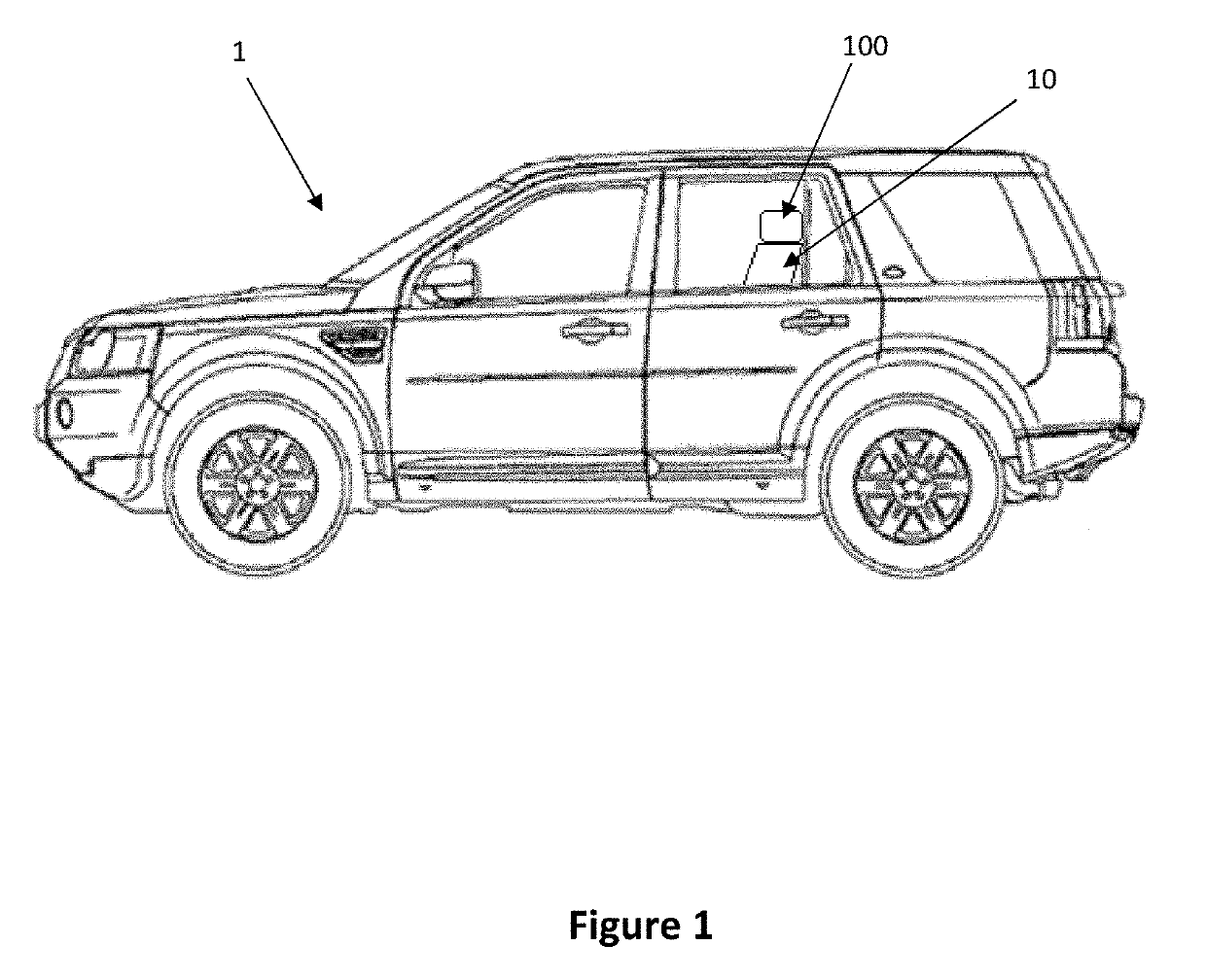
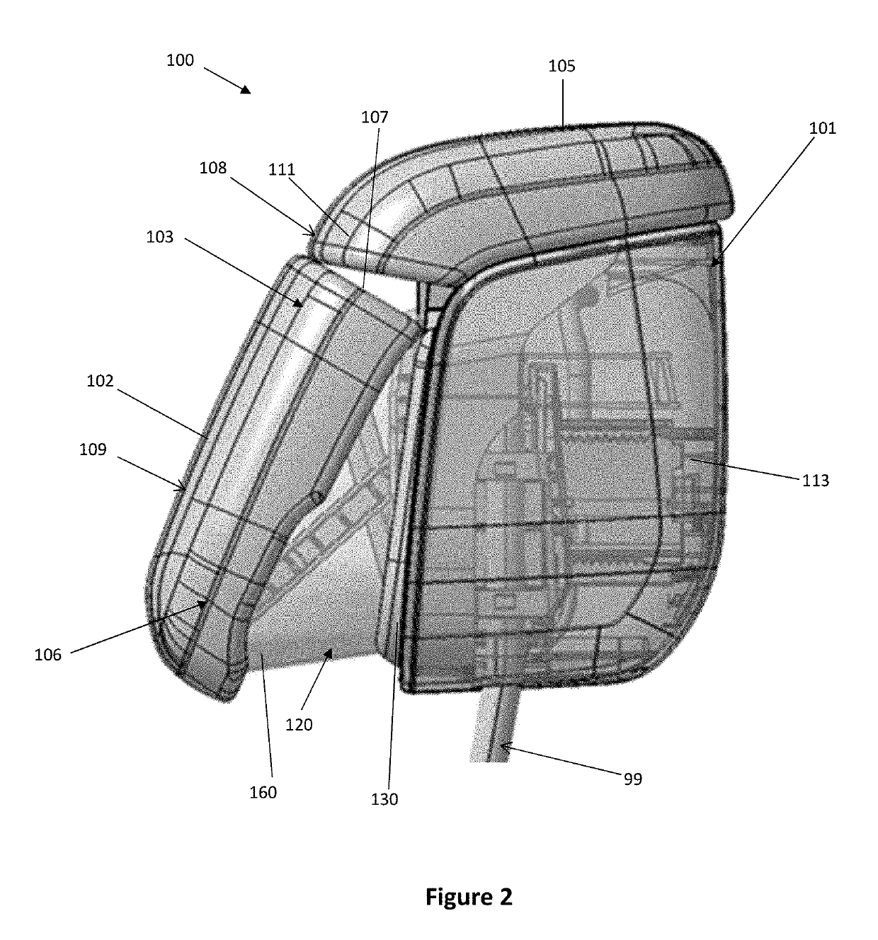
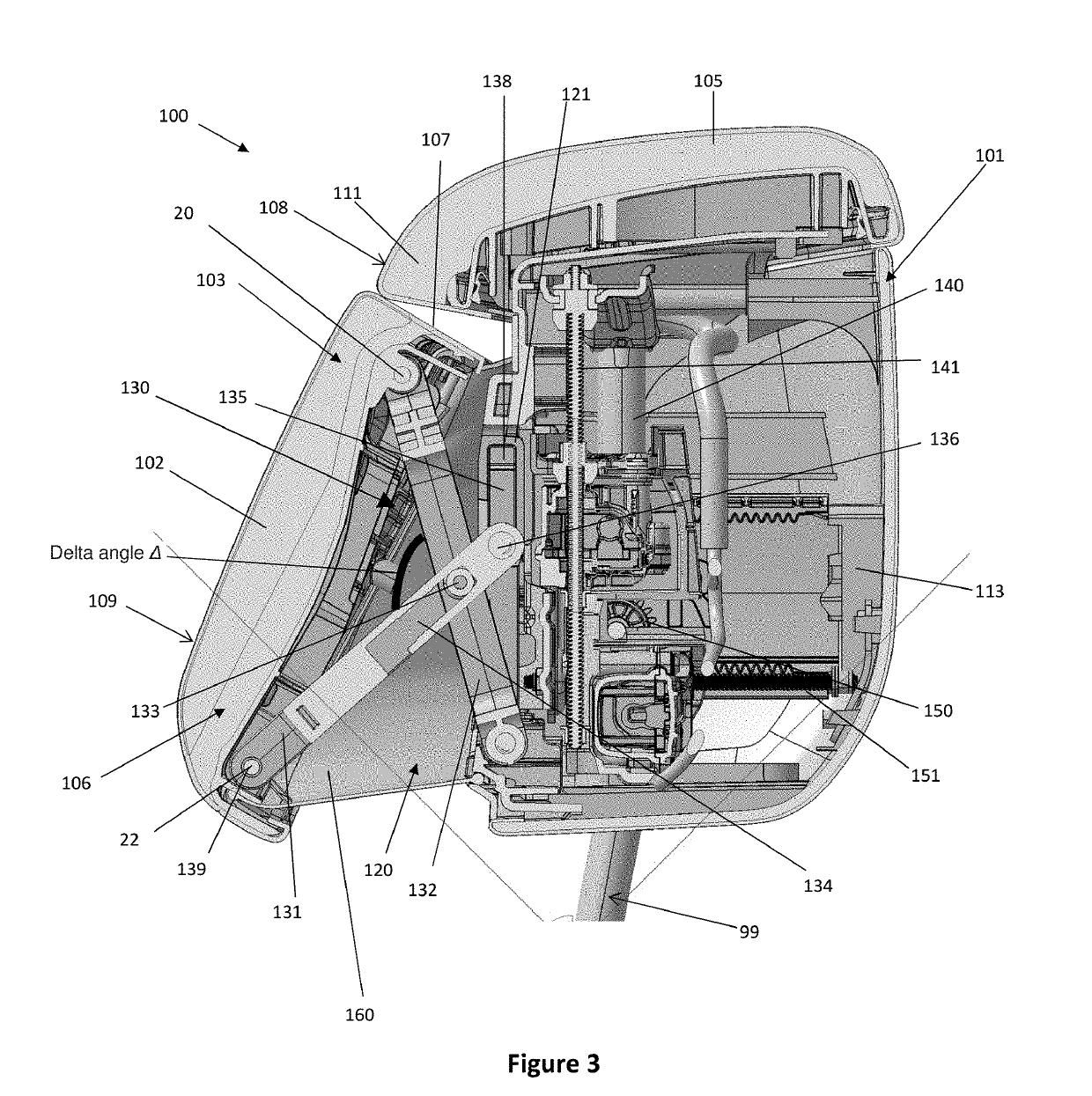
[0049]A head restraint assembly 100 of the present invention, for use in a seat assembly 10 of a vehicle 1, defines a rest surface 108, 109 for a user's head. The head restraint assembly 100 is operable between stowed and deployed positions, and a range of positions in between, so as to provide various different head rest positions for the user to provide comfort to the user in a variety of different seat positions.

[0050]FIG. 1 illustrates the seat assembly 10 belonging to the vehicle 1 comprising the head restraint assembly 100 of the present invention, Referring to FIGS. 2 to 4, the head restraint assembly 100 comprises a housing 101 and a movable head rest portion 102 (not shown in FIG. 4). The movable head rest portion 102 defines at least a part of a rest surface 108, 109 for supporting a seat user's head and provides support to the head of a passenger typically seated in a rear in-vehicle passenger seat when it is reclined in a “slouch” mode or position (i.e. typically sitting...


PUM


Abstract

A head restraint assembly for a seat which includes a housing and a movable head rest portion which defines at least a part of a rest surface for a seat user's head. The movable head rest portion is pivotally mounted to the housing via a linkage mechanism that is configured to allow pivotal movement of the movable head rest portion to enable the angle of the rest surface relative to the housing to be adjusted.

Description

CROSS REFERENCE TO RELATED APPLICATION[0001]This application claims priority to United Kingdom Patent Application No. GB 1716363.5, filed on 6 Oct. 2017.TECHNICAL FIELD[0002]The present disclosure relates to a head restraint assembly for a seat. In particular, but not exclusively, the invention relates to a head restraint assembly for a vehicle seat. Aspects of the invention relate to a head restraint assembly, to a seat assembly including a head restraint assembly and to a vehicle including a head restraint assembly.BACKGROUND[0003]Conventional in-vehicle head restraints perform the function of enhancing passenger safety and are often designed to be attached or integrated into the top of each driver and passenger seat. More specifically, head restraints are designed to limit the rearward movement of the head of an adult occupant relative to their torso, in the instance of a high-speed collision or crash for example, in order to prevent or mitigate whiplash or injury to the passenge...

Claims


Application Information

Patent Timeline
IPC IPC(8): B60N2/865
CPCB60N2/865B60N2002/899B60N2/847B60N2/876A47C1/036A47C7/38B60N2/859B60N2/862
Inventor SPACKMAN, RYANTURCU, CRISTIAN
Owner JAGUAR LAND ROVER LTD
Learn More