Rotor tip

Inactive Publication Date: 2004-08-26
ROCKTEK
View PDF6 Cites 1 Cited by
  • Summary
  • Abstract
  • Description
  • Claims
  • Application Information

AI Technical Summary

Benefits of technology

[0027] In alternate embodiment of the present invention there may be imbedded within the polyurethane a biasing means. In one embodiment this may be in the form of a leaf spring. After the spring is depressed during a rock impact, the spring may assist the polyurethane to return to its original shape through release of the stored energy within the spring.
[0028] The applicant has found that the present invention gives considerable advantages and vastly increases the life of the rotor tip in both high impact and general abrasive wear situations.

Problems solved by technology

One of the problems associated with typical centrifugal crushers is that there is considerable wear and tear on the exit apertures of the rotor.
Unfortunately, tungsten tips wear down along with the tip holders and these have to be replaced at regular intervals.
Further, the downtime in the operation of the rock crusher during changeover of tip holders is also an expensive exercise.
One of the reasons that the tips break down is that they tend to fracture due to shock loading.
This process can impart thermal shock to the tungsten, making it more susceptible to shock loading during the operation of the rock crusher.
With present systems the size of rock is dependent upon the impact force it imparts on the rotor tip as heavier rocks can cause the tip to wear out too quickly.
Finally, the greater the mass of the rock, the larger the impact when the rock hits the rock bed after exiting the rotor, which again leads to greater crushing power.
Another factor contributing to the wear and tear on the rotor tip is the direct exposure it has to rock exiting the rotor.
For example, some materials may deform over time and lose memory.

Method used


Image

  • Rotor tip
  • Rotor tip
  • Rotor tip

Examples


Embodiment Construction

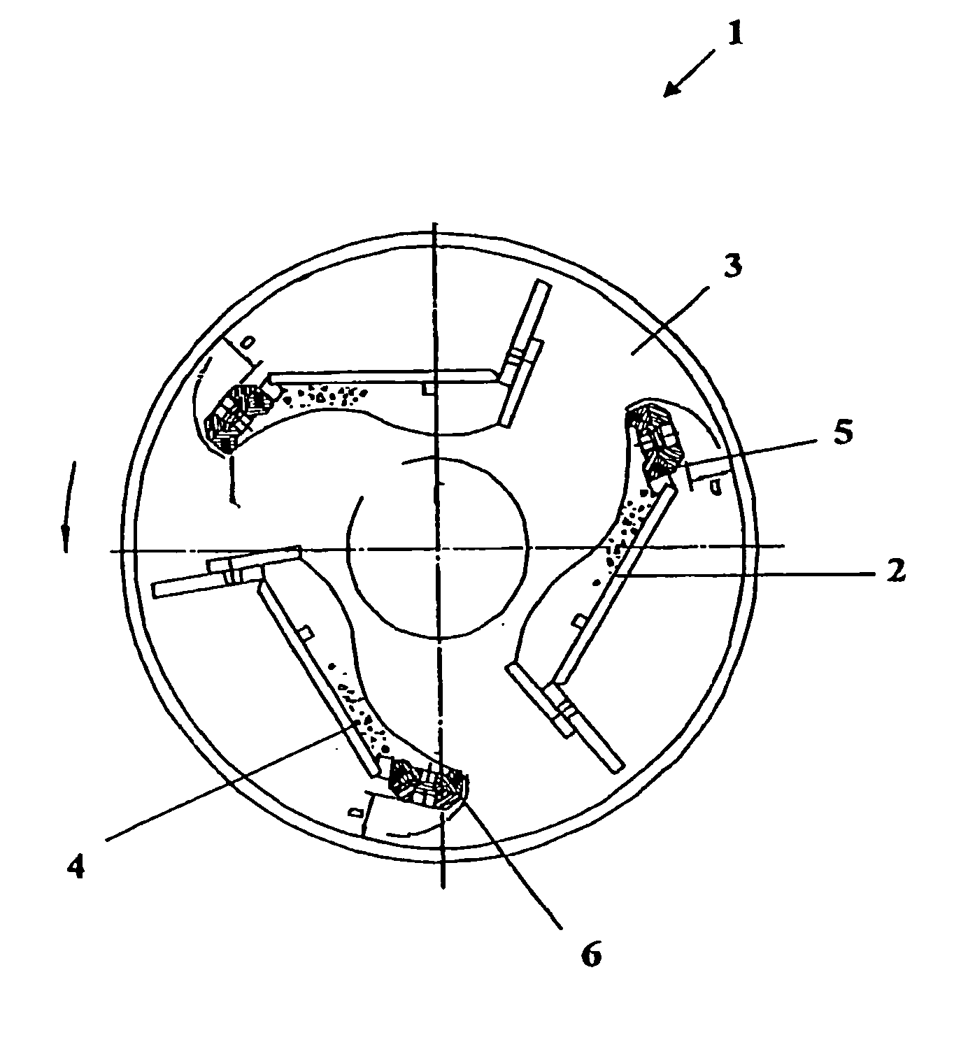
[0045] With respect to FIG. 1 there is illustrated a rotor generally indicated by arrow 1.

[0046] The rotor (1) has three blades (2) which are positioned just prior to exit apertures (3) of the rotor (1).

[0047] When the rotor (1) is rotating in the direction of the arrow shown, rock (4) builds up in waves on the blades (2).

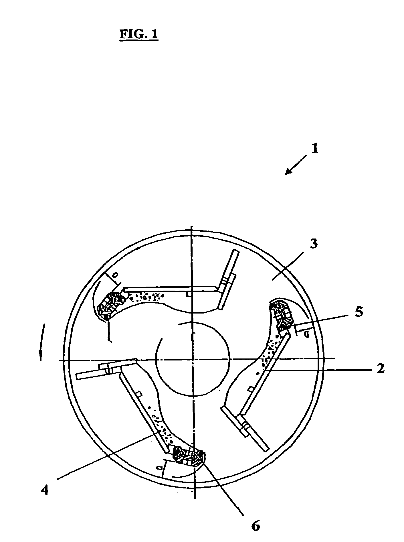
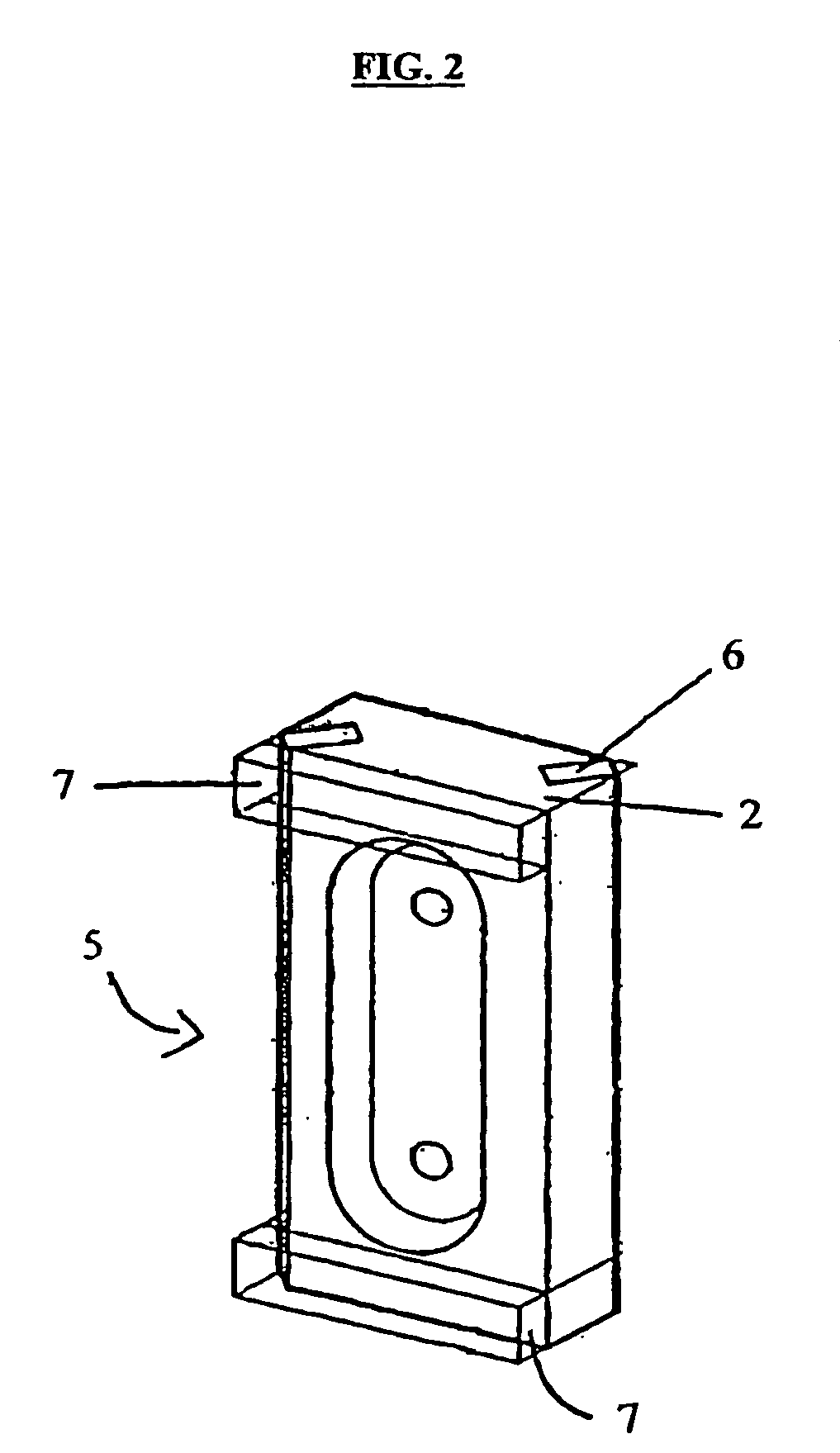
[0048] Positioned next to the blades (2) and before the trailing edge of the aperture (3) is a tip holder (5) which is mounted to the inner wall of the rotor (1). The tip holder (5) holds a tungsten tip (6) (not clearly shown).

[0049] It can be seen from the configuration shown in FIG. 1 that rock exiting the rotor (1) passes over the tip (6).

[0050] Referring now to FIG. 2, sandwiched between the tip holder (5) and the rotor wall or the rotor (1) is a resilient material (7). In this embodiment the resilient material is 10 mm polyurethane having a hardness of SHD95C.

[0051] It can be seen that there are only two bearing surfaces between the tip holder (5) and the roto...


PUM


Abstract

The present invention relates to a method of assembling a rotor for use in a rock crusher characterised by the step of positioning a resilient material between a rotor tip holder and the rotor.

Description

[0001] This invention relates to improvements to rotor tips.[0002] Reference throughout the specification should be made to the use of the present invention for the improvements to rotor tips in centrifugal rock crushers.[0003] Centrifugal rock crushers operate by having a spinning rotor into which rock of predetermined size range is gravity fed. Within the rotor are a number of blades (typically three) positioned close to apertures in the outer perimeter of the rotor.[0004] As the rotor rotates, rock builds up on the blades within the rotor before being eventually flung out of the aperture into a crushing chamber. The impact of the rocks on each other or on anvils causes the rocks to break down to a desired size.[0005] One of the problems associated with typical centrifugal crushers is that there is considerable wear and tear on the exit apertures of the rotor. In order to address this problem rotors have hard wearing rotor tips and tip holders positioned at the trailing edge of th...

Claims


Application Information

Patent Timeline
IPC IPC(8): B02C13/18B02C13/28
CPCB02C13/1807B02C13/2804B02C13/28
Inventor ROBSON, ANGUS PETER
Owner ROCKTEK
Why Eureka
Try Eureka