Flow field plate for improved coolant flow

a flow field and flow plate technology, applied in the field of flow field plate designs, can solve the problems of affecting the flow of reactants, non-uniform distribution, and impede the flow of other fluids in the coolant transition region, and achieve the effects of improving the flow of coolants, and reducing the pressure drop in the transition region

Active Publication Date: 2014-11-20
CELLCENTRIC GMBH & CO KG +1
View PDF7 Cites 8 Cited by
  • Summary
  • Abstract
  • Description
  • Claims
  • Application Information

AI Technical Summary

Benefits of technology

[0013]The present invention provides for improved coolant flow and reduced pressure drop in the transition regions in a bipolar plate assembly without adversely affecting the flow of the reactants in the coolant transition regions and while maintaining the overall volume of the stack. This can be accomplished by offsetting the transition fuel channels from the transition oxidant channels in the transition regions. Consequently, this can be accomplished using conventional planar MEAs.

Problems solved by technology

As will be more apparent when discussing the Figures below, the presence of such ducts can impede the flow of other fluids in the coolant transition region.
This can result in non-uniform distribution to and hence non-uniform sharing of the coolant in the coolant flow field channels in the active area of the fuel cell.
This in turn increases the risk of overheating (hot spots) and over-drying in the cells on hot days.
Also, it can lead to formation of wet spots in the cells, making it difficult to prepare the stack for shutdown in below freezing conditions and also difficult to recover during startup from below freezing conditions.
The pressure drop can be reduced to some extent by sacrificing space provided for the flow of reactants in the coolant transition region but, depending on port and transition designs, this can result in an unacceptable blocking of the flow of one or both of the reactants.
However, the power density of the stack is then undesirably reduced, along with a possible undesirable increase in mass of the stack.
However, the fuel and oxidant channels necessarily bend at the interfaces between the transition and active channels thus are not straight in these brief interface areas between the transition regions and the active region in this embodiment.

Method used


Image

  • Flow field plate for improved coolant flow
  • Flow field plate for improved coolant flow
  • Flow field plate for improved coolant flow

Examples


example

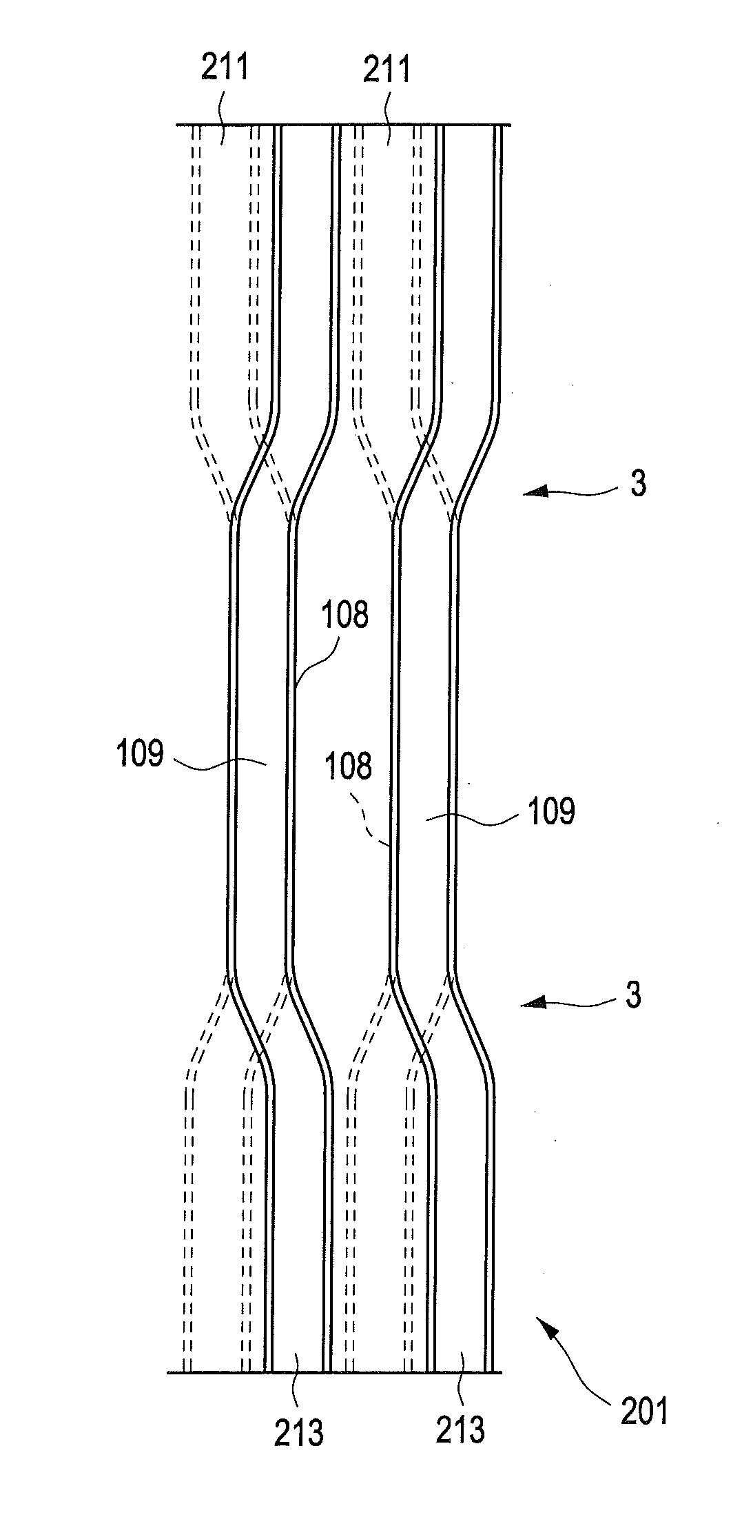
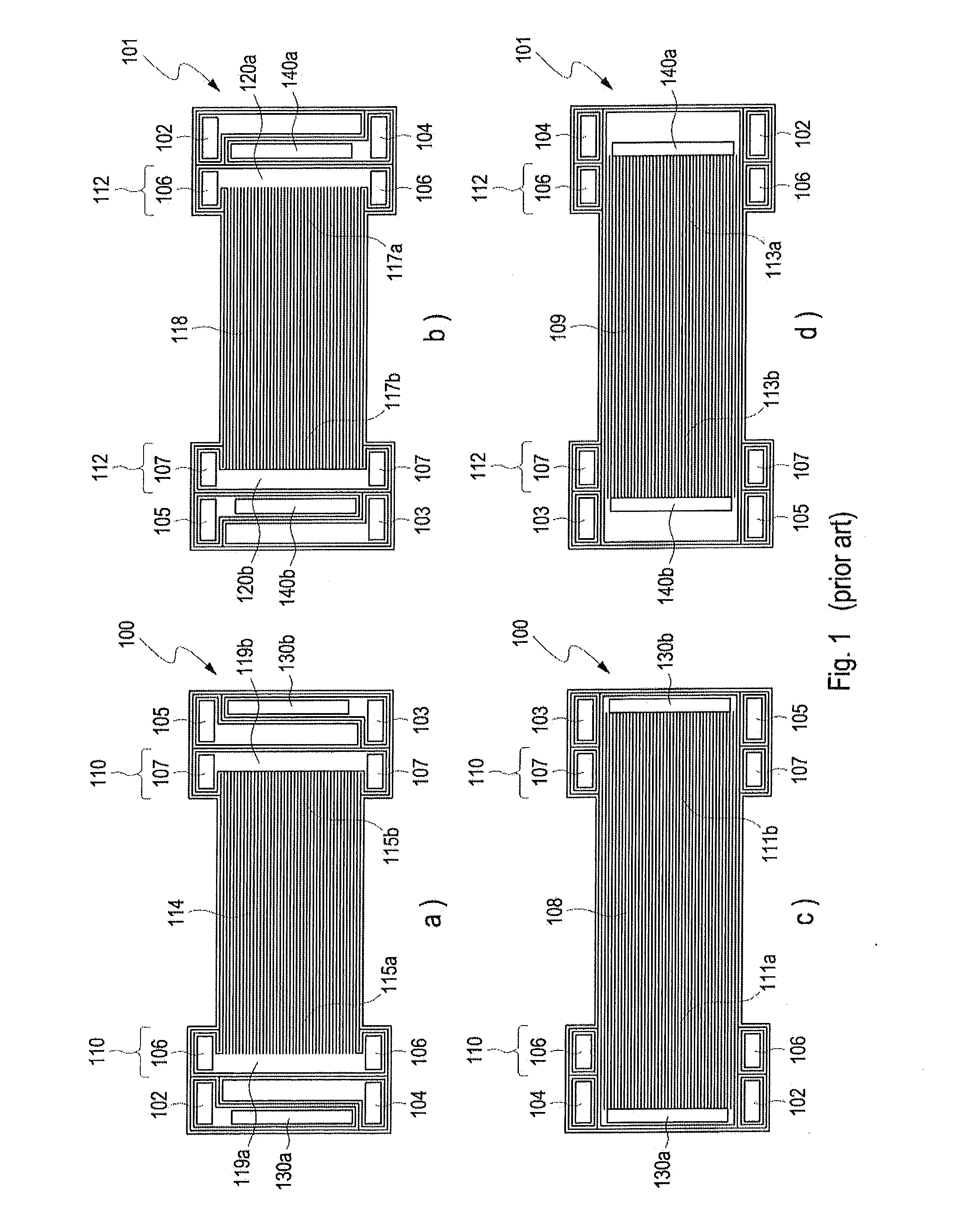
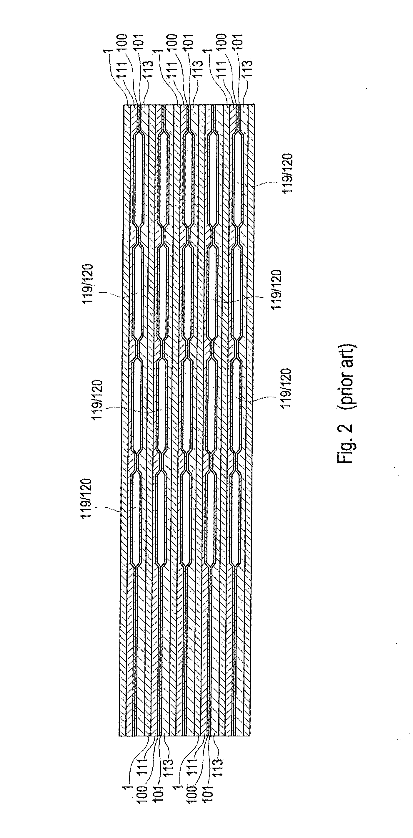
[0055]Analyses were performed to compare the expected pressure drop for the coolant in a conventional fuel cell to the pressure drop expected in an exemplary fuel cell of the invention. The conventional fuel cell was assumed to be of a design similar to that shown in FIGS. 2, 3a, and 3b and intended for use in a high power density automotive application. The inventive fuel cell was assumed to be similar to that of the conventional fuel cell except that the transition fuel channels were offset from the transition oxidant channels as shown in FIGS. 3c and 4.

[0056]In operation, reactant and coolant flows typical for such high power density automotive applications were also assumed. Computational fluid dynamics methods were then used to determine the expected pressure drops for the coolant in the transition and active regions in the two fuel cell designs.

[0057]In both fuel cells, the coolant pressure drop in the active region was determined to be about 44 mB. In the conventional fuel ce...


PUM

PropertyMeasurementUnit
output voltageaaaaaaaaaa
pressure dropaaaaaaaaaa
electric poweraaaaaaaaaa

Abstract

Bipolar plate assemblies are disclosed in which the transition fuel channels are offset from the transition oxidant channels in the transition regions on the active sides of the plates. This configuration allows for a reduced pressure drop in the coolant flow in the transition regions on the inactive, coolant side of the plates and thereby improves coolant flow sharing. The assemblies are suitable for use in high power density solid polymer electrolyte fuel cell stacks.

Description

BACKGROUND[0001]1. Field of the Invention[0002]This invention relates to flow field plate designs for improving coolant flow by reducing the pressure drop in the coolant transition regions between the ports and the flow fields in bipolar plate assemblies for solid polymer electrolyte fuel cell stacks.[0003]2. Description of the Related Art[0004]Fuel cells such as solid polymer electrolyte or proton exchange membrane fuel cells electrochemically convert reactants, namely fuel (such as hydrogen) and oxidant (such as oxygen or air), to generate electric power. Solid polymer electrolyte fuel cells generally employ a proton conducting, solid polymer membrane electrolyte between cathode and anode electrodes. A structure comprising a solid polymer membrane electrolyte sandwiched between these two electrodes is known as a membrane electrode assembly (MEA). In a typical fuel cell, flow field plates comprising numerous fluid distribution channels for the reactants are provided on either side ...

Claims


Application Information

Patent Timeline
Patent Type & Authority Applications(United States)
IPC IPC(8): H01M8/02
CPCH01M8/0267H01M2008/1095H01M8/0258H01M8/0206H01M8/241H01M8/2457H01M8/2483Y02E60/50
Inventor FELLOWS, RICHARDFARRINGTON, SIMON
Owner CELLCENTRIC GMBH & CO KG
Why Eureka
Try Eureka