Spasticity measurement device

a measurement device and spasticity technology, applied in the field of measuring devices, can solve the problem that the apparatus cannot be used to quantitatively comprehend the symptoms of a patient, and achieve the effects of excellent reproducibility, easy measurement of spasticity degree, and easy evaluation of spasticity degr

Inactive Publication Date: 2014-11-20
TOMEI BRACE
View PDF3 Cites 9 Cited by
  • Summary
  • Abstract
  • Description
  • Claims
  • Application Information

AI Technical Summary

Benefits of technology

[0019]According to the first aspect of the invention, the spasticity measurement apparatus includes the leg mounting fixture having the lower leg mounting portion and the foot receiving portion coupled relatively rotatably to each other and, when the lower leg mounting portion and the foot receiving portion are relatively rotated, the rotation is inhibited by the rotation inhibition apparatus, and the muscular contraction force acting in the rotation direction is measured in this state by the muscular contraction force measurement apparatus. Therefore, since a subject having the spasticity induced by the relative rotation of the foot receiving portion and the lower leg mounting portion is caused to generate rhythmic repeated contraction with lengths of lower leg flexor muscles fixed in a stretched state, a spasticity degree can easily be measured by measuring the muscular contraction force acting in the rotation direction of the foot receiving portion by the muscular contraction force measurement apparatus. The quantitative measurement of the spasticity degree can also easily be performed.
[0020]According to the second aspect of the invention, in the spasticity measurement apparatus, the leg mounting fixture having the lower leg mounting portion and the foot receiving portion coupled relatively rotatably to each other is supported by the leg mounting fixture support stand receiving the heel receiving portion and the toe receiving portion of the foot receiving portion and, therefore, when the leg mounting fixture is mounted on the lower limb of the subject, the lower limb is supported by the leg mounting fixture support stand. Since the leg mounting fixture support stand includes the support release apparatus for instantaneously releasing support by the heel support portion receiving the heel receiving portion, when support by the heel support portion is released by the support release apparatus, the heel receiving portion falls due to the weight of the leg of the subject and the toe receiving portion is kept supported by the toe support portion and, therefore, the lower limb and the foot of the subject are relatively rotated in the stretching direction of the lower leg flexor muscles i.e. in the dorsiflexion direction, thereby causing the lower leg mounting portion and the foot receiving portion mounted thereon to relatively rotate. Because the spasticity is induced by instantaneously stretching the lower leg flexor muscles in this way, the spasticity degree can quantitatively be measured by measuring contraction force of muscular repeated contraction generated in this case. In other words, according to the pres

Problems solved by technology

Thus, the apparatuses cannot be used for quantitative comprehension of a symptom of a patient i

Method used


Image

  • Spasticity measurement device
  • Spasticity measurement device
  • Spasticity measurement device

Examples


Embodiment Construction

[0044]An embodiment of the present invention will now be described in detail with reference to the drawings. In the following embodiment, the figures are simplified or deformed as needed and portions are not necessarily precisely depicted in terms of dimension ratio, shape, etc.

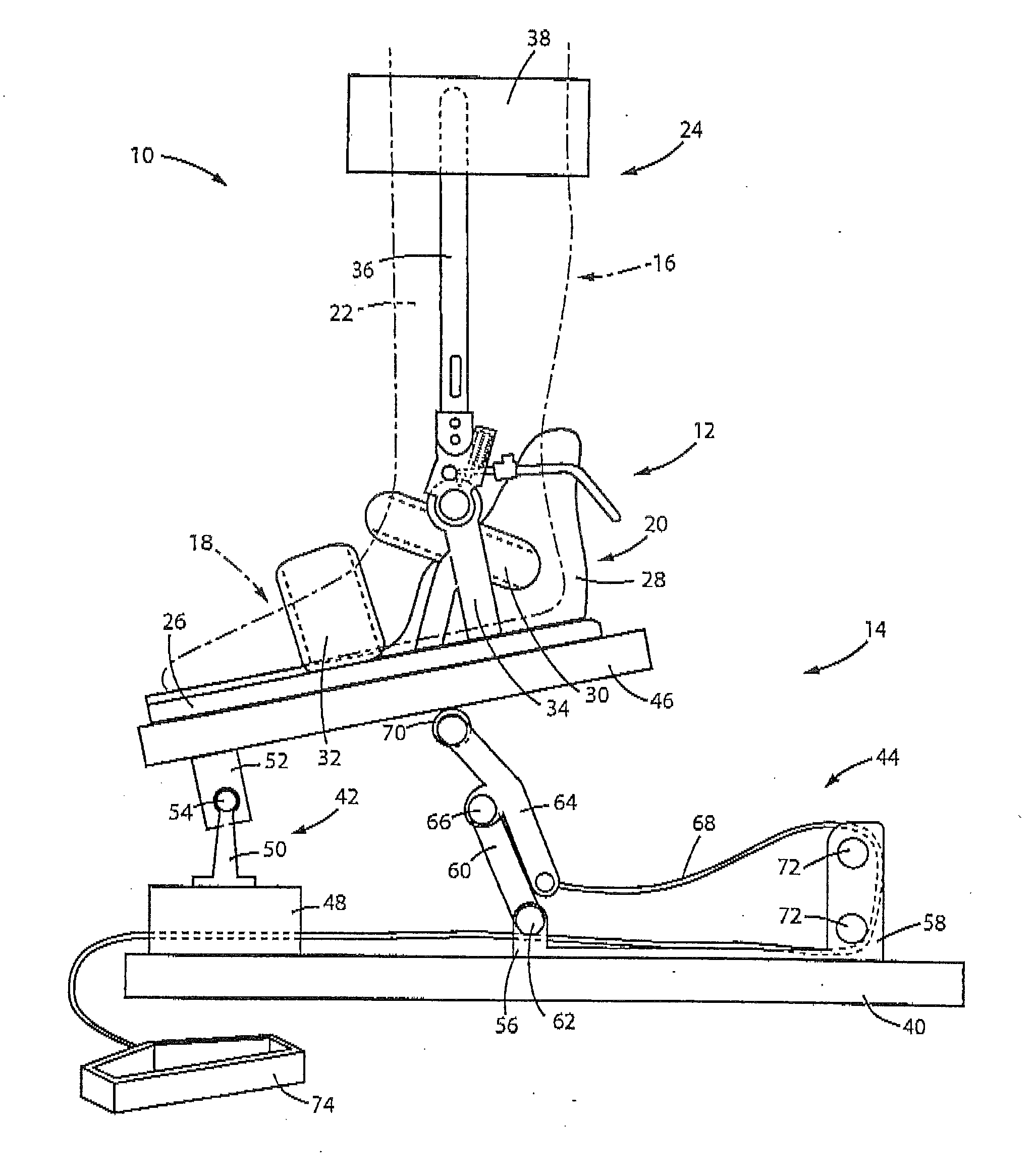
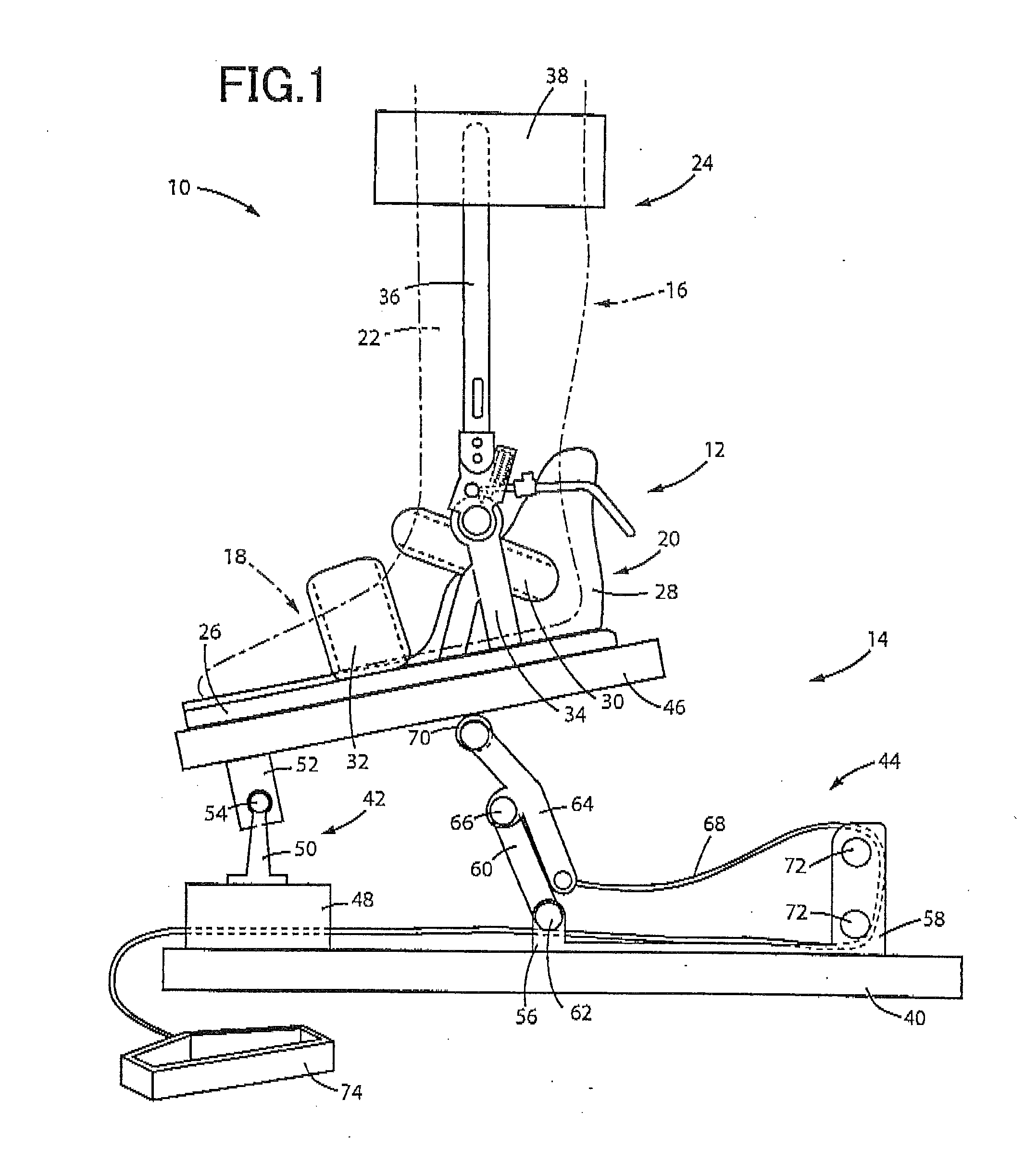
[0045]FIG. 1 is a diagram of an overall configuration of a spasticity measurement apparatus 10 of an embodiment of the present invention. In FIG. 1, the spasticity measurement apparatus 10 includes a leg mounting fixture 12 and a leg mounting fixture support stand 14.

[0046]The leg mounting fixture 12 has a foot receiving portion 20 retaining a foot 18 of a lower limb 16 of a subject indicated by a dashed-dotted line of FIG. 1, and a lower leg mounting portion 24 for mounting on a lower leg portion 22. The foot receiving portion 20 includes a plate-like member 26 made of rubber etc. and has a heel receiving portion 28 for receiving a heel and belts 30, 32 for fixing the foot 18 to the side surfaces and the fro...


PUM


Abstract

A spasticity measurement apparatus includes: a leg mounting fixture including a lower leg mounting portion mounted on a lower leg of a subject for fixation, and a foot receiving portion coupled to a lower end portion of the lower leg mounting portion and having a heel receiving portion and a toe receiving portion for respectively receiving a heel and a toe of a foot leading to the lower leg, the toe receiving portion being disposed relatively rotatably around the heel receiving portion in an approaching rotation direction bringing the toe receiving portion closer to the lower leg mounting portion; a rotation inhibition apparatus inhibiting relative rotation when the foot receiving portion rotates relative to the lower leg mounting portion in the approaching direction; and a muscular contraction force measurement apparatus measuring a muscular contraction force acting in a rotation direction.

Description

TECHNICAL FIELD[0001]The present invention relates to a measurement apparatus for easily evaluating spasticity or particularly spasticity of a lower limb.BACKGROUND ART[0002]Spasticity is a side effect associated with paralysis, means muscle stiffness, uncontrollable leg motion, etc., and includes symptoms such as an increase in muscle tone, sudden muscular contraction, deep tendon hyperreflexia, muscular spasm, scissors-like legs, and fixation of a joint. Treatment of spasticity generally includes motion exercise as well as drug treatment using drugs to remove neurological / muscle disorders.[0003]Such treatment of spasticity requires comprehension of current symptoms of a patient and constant comprehension of changes in symptom during treatment in terms of providing proper treatment. Although spasticity has hitherto been generally evaluated by using the following five-grade Ashworth Scale, this evaluation criterion relies on senses of a physician etc., and inevitably becomes subject...

Claims


Application Information

Patent Timeline
IPC IPC(8): A61B5/11A61B5/22A61B5/00
CPCA61B5/1107A61B5/6829A61B5/224A61B5/4884A61B5/4595A61B5/1124A61B5/6828A61B5/1101A61B5/4082
Inventor CHINO, NAOICHIMURAOKA, YOSHIHIROISHIHAMA, HIROKIOKUMURA, SHOJI
Owner TOMEI BRACE
Why Eureka
Try Eureka