Bobbin unwinding device of filament winding device

a technology of bobbin and filament winding, which is applied in the direction of filament handling, thin material processing, transportation and packaging, etc., can solve the problems of increasing unstable behavior of fiber bundle f, and the possibility of fiber bundle turnover f, so as to prevent the turnover of fiber bundles at a position in the vicinity

Active Publication Date: 2014-11-27
MURATA MASCH LTD +1
View PDF3 Cites 1 Cited by
  • Summary
  • Abstract
  • Description
  • Claims
  • Application Information

AI Technical Summary

Benefits of technology

[0015]The present invention exerts effects described below.
[0016]According to the first aspect, the fiber bundle would not twist between the bobbin and the auxiliary roller. Alternatively, the fiber bundle is twisted between the auxiliary roller and the fixed guide. As such, the grip force of the auxiliary roller to the fiber bundle is maintained. Accordingly, the behavior of the fiber bundle can be stabilized, and turnover of the fiber bundle can be prevented.
[0017]According to the second aspect, the fiber bundle would not twist between the bobbin and the auxiliary roller even at a position in the vicinity of folding-back position of traversing. Alternatively, the fiber bundle is twisted between the auxiliary roller and the fixed guide. As such, the grip force of the auxiliary roller to the fiber bundle is maintained. Accordingly, the behavior of the fiber bundle can be stabilized, and turnover of the fiber bundle can be prevented.
[0018]According to the third aspect, turnover of the fiber bundle at a position in the vicinity of one folding-back position of traversing can be suppressed. As such, a possibility of turnover of the fiber bundle can be reduced. Accordingly, the behavior of the fiber bundle can be stabilized, and turnover of the fiber bundle can be prevented.
[0019]According to the fourth aspect, the difference of distance due to the width of the fiber bundle is reduced even at the position in the vicinity of folding-back position of traversing. As such, twisting of the fiber bundle is suppressed. Accordingly, the behavior of the fiber bundle can be stabilized, and turnover of the fiber bundle can be prevented.
[0020]According to the fifth aspect, while the fiber bundle unwound from the bobbin is en route to the fixed guide, the fiber bundle is touched to the auxiliary roller for a long distance. As such, the grip force of the auxiliary roller to the fiber bundle increases. Accordingly, the behavior of the fiber bundle can be stabilized, and turnover of the fiber bundle can be prevented.

Problems solved by technology

That is to say, there is a possibility of turnover of the fiber bundle.
In that case, a difference between a distance from a1 to b1 and a distance from a2 to b2 becomes maximum at positions in the vicinity of folding-back positions TL, TR of traversing due to the traversing of the fiber bundle F. Accordingly, there is the case that the behavior of the fiber bundle F becomes unstable, and there is a problem in which a possibility of turnover of the fiber bundle F increases.
As such, there is the threat that the fiber bundle F might be wound around the liner in a twisted state, and that might cause degradation of quality and deterioration of strength of a product.
Accordingly, there is the case that the behavior of the fiber bundle F becomes unstable, and there is a problem in which the possibility of turnover of the fiber bundle F increases.

Method used


Image

  • Bobbin unwinding device of filament winding device
  • Bobbin unwinding device of filament winding device
  • Bobbin unwinding device of filament winding device

Examples


first embodiment

[0060]Next, a detailed explanation will be given of the bobbin unwinding device 32A which is the present invention.

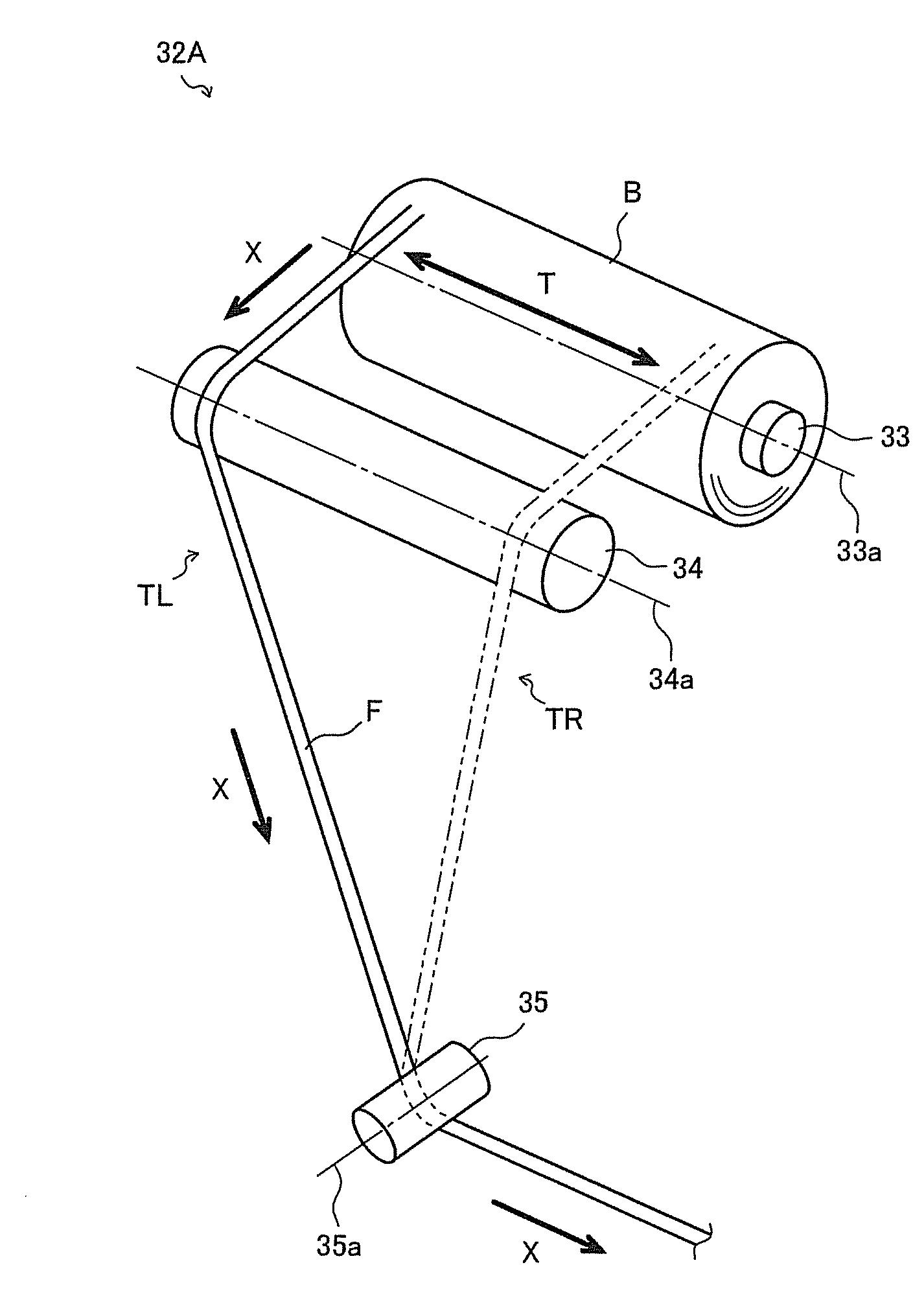
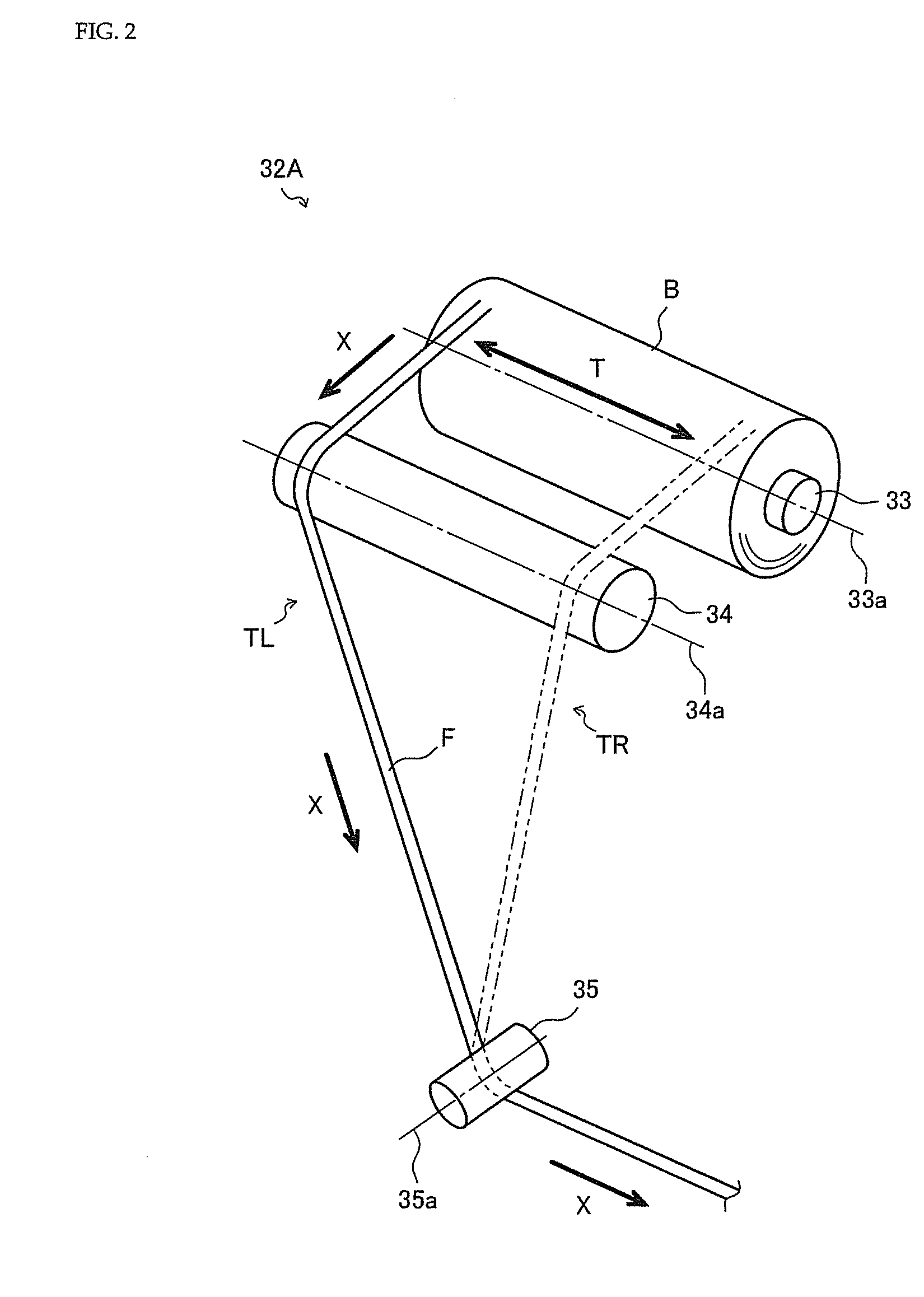
[0061]FIG. 2 shows the configuration of the bobbin unwinding device 32A according to the present embodiment. An arrow X shown in the drawing indicates the feeding direction of the fiber bundle B. An arrow T shown in the drawing indicates the traversing of the fiber bundle F when the fiber bundle F is unwound from the bobbin B.

[0062]The bobbin support shaft 33 is a support member which supports the bobbin B to be rotatable. The bobbin support shaft 33 is formed in an approximately cylindrical shape, and the bobbin support shaft 33 is fit into the bobbin B. As described above, the bobbin B supported by the bobbin support shaft 33 rotates in a state that the fiber bundle F is pulled, whereby the fiber bundle F is unwound (rollingly reeling-off type). And the fiber bundle F unwound from the bobbin B is led to the auxiliary roller 34.

[0063]The auxiliary roller 34 is a rotary...

second embodiment

[0067]Next, a detailed explanation will be given of the bobbin unwinding device 32B which is the present invention.

[0068]FIG. 3 shows the configuration of the bobbin unwinding device 32B according to the present embodiment. An arrow X shown in the drawing indicates the feeding direction of the fiber bundle F. An arrow T shown in the drawing indicates the traversing of the fiber bundle F when the fiber bundle F is unwound from the bobbin B.

[0069]The configuration of the bobbin unwinding device 32B according to the present embodiment is approximately the same as that of the above-mentioned bobbin unwinding device 32A according to the first embodiment. Accordingly, an explanation will be given focusing on differences relative to the bobbin unwinding device 32A of the first embodiment.

[0070]As shown in FIG. 3, an auxiliary roller 34 which is a member of the bobbin unwinding device 32B is formed in an approximately spindle shape. The auxiliary roller 34 configures an outer periphery surf...


PUM


Abstract

This bobbin unwinding device (32A (32B)) is provided with a bobbin support shaft (33) which rotatably supports a bobbin (B) around which a band-like fiber bundle (F) is wound, a fixed guide (35) which changes the running direction of the fiber bundle (F) unwound from the bobbin (B), and an auxiliary roller (34) arranged between the bobbin (B) and the fixed guide (35), wherein the fixed guide (35) is arranged such that the shaft center of the fixed guide (35) is substantially perpendicular to the shaft center of the bobbin support shaft (33), and the auxiliary roller (34) is arranged such that the shaft center of the auxiliary roller (34) is parallel or substantially parallel to the shaft center of the bobbin support shaft (33).

Description

TECHNICAL FIELD[0001]The present invention relates to a technique for a bobbin unwinding device of a filament winding device.BACKGROUND ART[0002]Conventionally, a filament winding device which winds a band-like fiber bundle around the outer periphery of a liner has been known. The filament winding device is provided with a creel stand, and a plurality of bobbins around which the fiber bundle is wound are arranged in the creel stand (for example, see Patent Literature 1). With regard to the filament winding device, the fiber bundle is unwound from each bobbin arranged in the creel stand in the form of rollingly reeling-off type, whereby the fiber bundle is wound around the outer periphery surface of the liner.[0003]In the case of such filament winding device, especially in the case of a multiple yarn supply type filament winding device, the fiber bundles reeled off from the plurality of bobbins have to be guided and simultaneously wound onto the liner. Therefore, the creel stand tend...

Claims


Application Information

Patent Timeline
Patent Type & Authority Applications(United States)
IPC IPC(8): B65H57/14B65H57/18
CPCB65H57/18B65H57/14B65H49/18B65H2701/31B65H2701/37
Inventor TANIGAWA, MOTOHIRONAKAMURA, DAIGOROHATTA, KEN
Owner MURATA MASCH LTD
Why Eureka
Try Eureka