
Controllable optical sensing

a controllable, optical sensor technology, applied in the direction of optical radiation measurement, instruments, using reradiation, etc., can solve the problems of increasing the complexity of design and price, the inability to obtain depth sensing on objects in close proximity to the depth sensor, and the inability to provide gesture recognition for controlling the computer

Active Publication Date: 2014-11-27
META PLATFORMS TECH LLC
View PDF33 Cites 19 Cited by
  • Summary
  • Abstract
  • Description
  • Claims
  • Application Information

AI Technical Summary

Benefits of technology

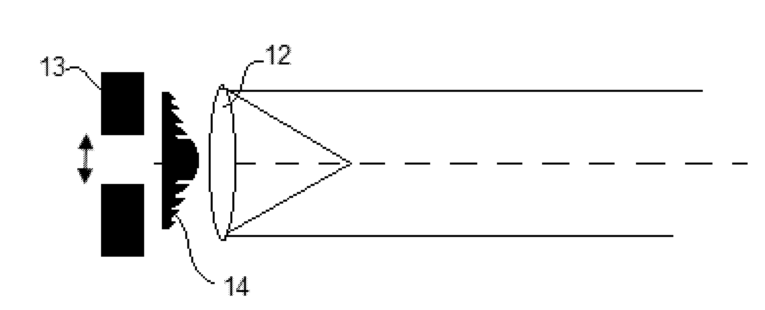
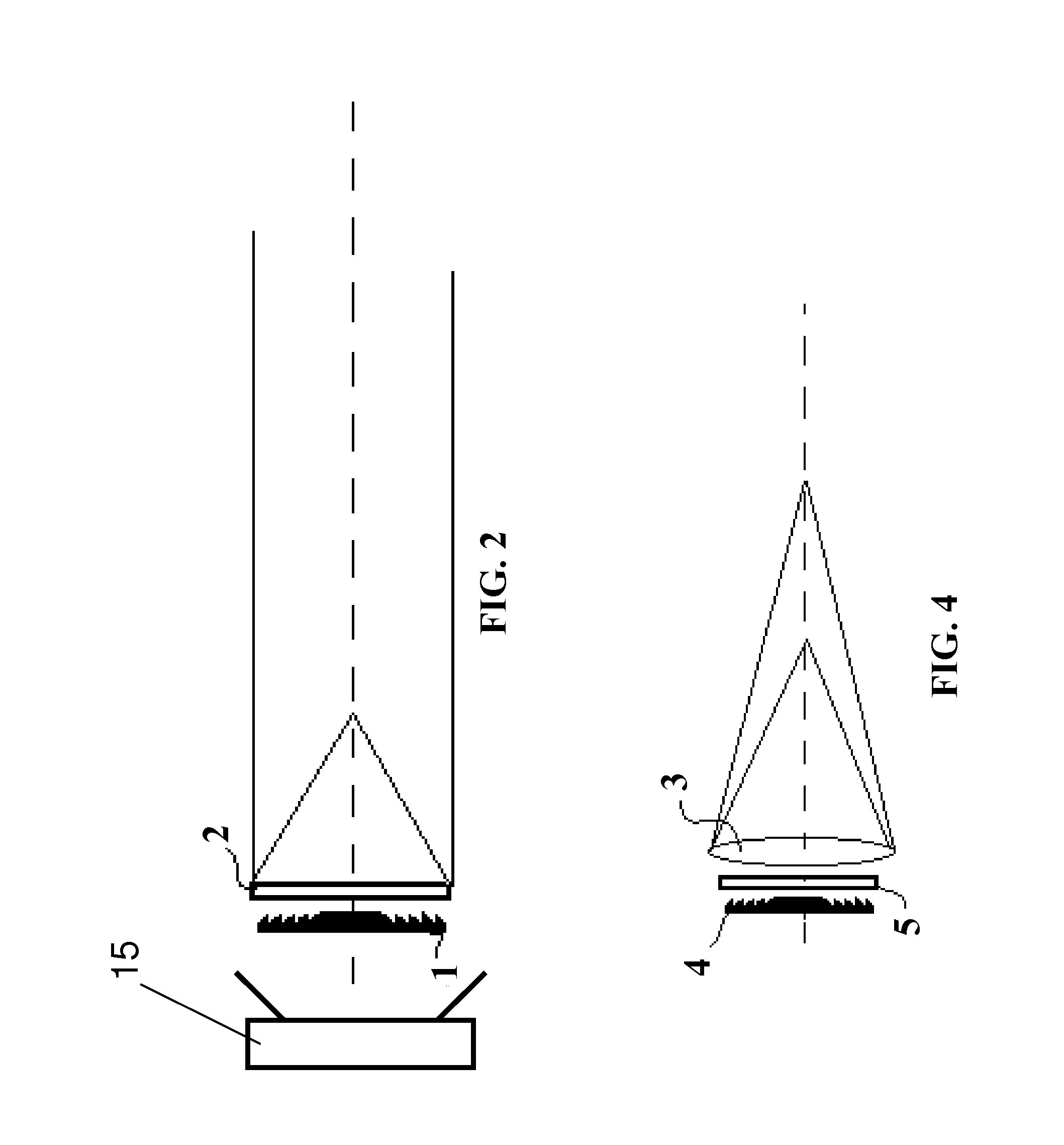
The present invention relates to an optical sensing device that uses a controllable lens to provide dynamic beam patterns for sensing objects or features in a space. The device includes a light source, a controllable lens, and a sensor to sense the focused light. The controllable lens can be controlled to focus light at different distances, creating multiple foci for detection. The device can be used in a three-dimensional space and has applications in optical sensing, augmented reality, and other fields. The invention provides a method for using the device to detect objects or features in a field of view by shining light onto the controllable lens and sensing the reflected light. The invention also provides a system for implementing the optical sensing device using hardware, software, or a combination of both.

Problems solved by technology

One limitation of this method is the inability to obtain depth sensing on objects at close proximity to the depth sensor.
Thus gesture recognition for controlling the computer cannot be provided from a short distance, which is the distance a person normally uses a computer.
Various techniques can be applied to overcome this limitation but they require additional methods and hardware components thus increasing the complexity of design and price.
The density limits the method from operating in a full dynamic range of proximities.
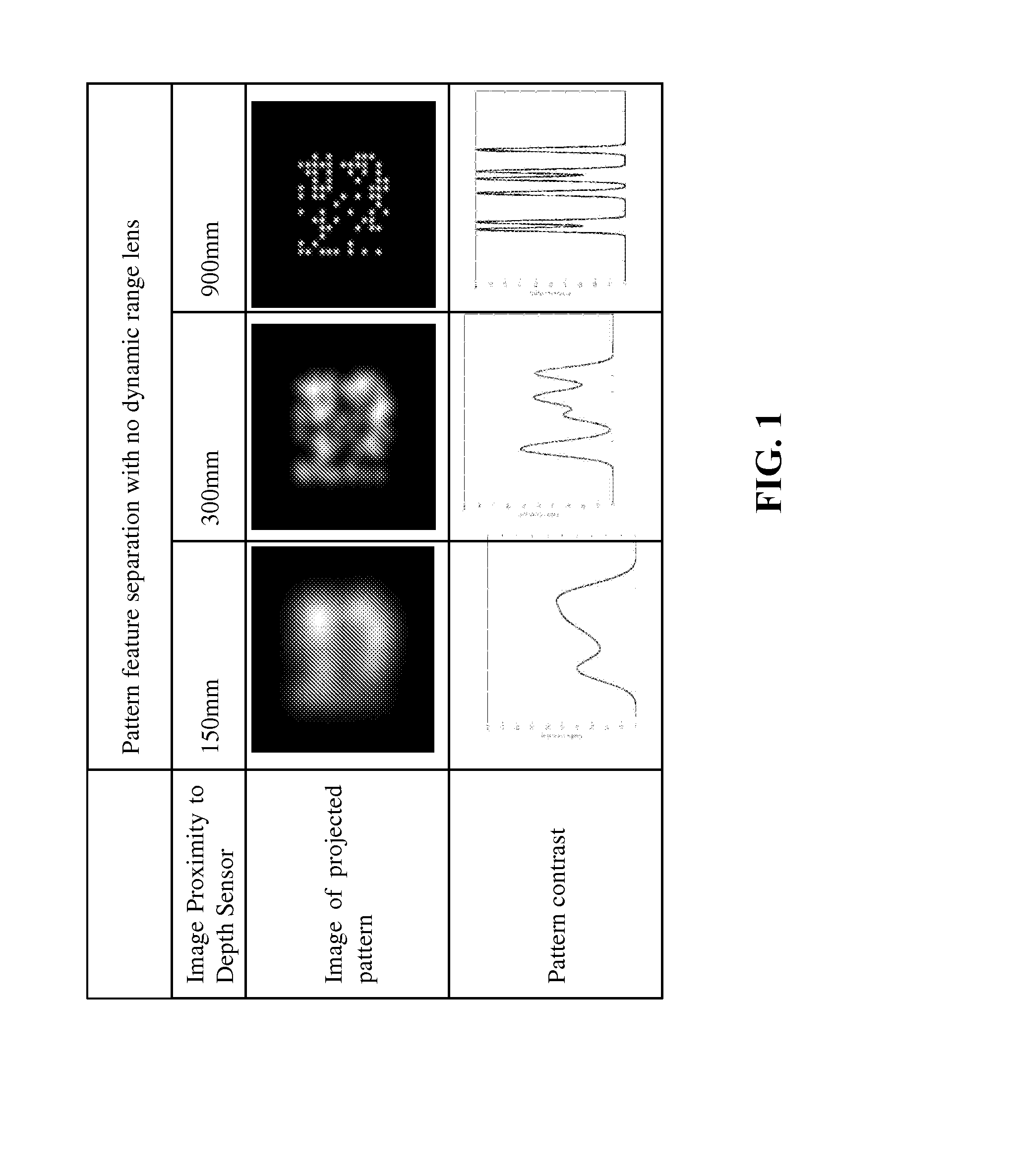
But when operating at close proximities, generally under 0.8 m, the projected features overlap and do not provide the pattern that is required for generating the necessary calculations for depth detection and motion tracking.
In these types of designs however, the resolution deteriorates throughout the distance since the spots diverge from each other, resulting in poor resolution at these larger distances.
However, in this type of setup the features at distant proximities are defocused, blurred and overlap, thus resulting in the same problems as with the first design but for distant proximity ranges.
Both of the mentioned methods are thus restricted to specific operating distances and no current method offers a solution for a single depth sensor to effectively operate on a full dynamic range of distances.
Depth sensing cannot thus be performed at the smaller range using this system.
The need for focus again limits the dynamic range of operation of the device.

Method used


Image

  • Controllable optical sensing
  • Controllable optical sensing
  • Controllable optical sensing

Examples


Embodiment Construction

[0053]The present invention, in some embodiments thereof, relates to an optical three-dimensional (3D) depth sensor and, more particularly, but not exclusively, to an optical 3D device for determining shapes and / or tracking the positions in three dimensional space of objects in view, and to a beam expander.

[0054]An embodiment is a depth imager device with extended dynamic range of its effective optical sensing, and comprises an image sensor, a light emitter projecting structured light at a predefined number of focal points and a processor able to process the resulting light patterns. Multi-focused structured light is projected into a view which includes an object of interest. The depth of the object is sensed by a structured illumination depth sensor which analyses the detected light structures that are in focus at the actual distance range of the object, the remaining light structures being out of focus.

[0055]Structured light may include a light pattern created by a laser or LED co...


PUM

PropertyMeasurementUnit
distanceaaaaaaaaaa
distanceaaaaaaaaaa
distanceaaaaaaaaaa

Abstract

An optical sensing device for using light to locate objects or features in a field of view comprises a light source; a controllable lens having two states and being controllable between them, for example a multifocal lens having two or more foci for focusing light from the light source; and a sensor able to sense light reflected from an object, to determine information of the object. The use of two or more foci adds dynamic range to optical sensing to allow for reliable detection over a wide range of distances.

Description

FIELD AND BACKGROUND OF THE INVENTION[0001]The present invention, in some embodiments thereof, relates to a controllable optical sensor and, more particularly, but not exclusively, to an apodized optical device which is controllable, in one example to provide defined patterns and in another example to provide an optical 3D device for determining and tracking the positions in three dimensional space of objects in view and / or determining their 3D structure, and in a third example for an optical beam expander.[0002]Current methods for optical 3D sensing and motion tracking consist of mainly two technologies, time-of-flight (TOF) and structured illumination.[0003]TOF uses a similar concept as in range finding technology, where a light pulse is illuminated towards an object surface (generally from an IR emitter) and photons reflected from the object surface are collected via a sensor, generally a unique CMOS sensor with a very high rate of acquired frames per second designed exclusively ...

Claims


Application Information

Patent Timeline
Patent Type & Authority Applications(United States)
IPC IPC(8): G01J1/04G01N21/55G01S17/89
CPCG01J1/0411G01N21/55G01J1/0448G01J1/044G01S17/46G01S17/89G01B11/25G01S7/4814G02B3/10G02B5/1876G02B27/4205G02B27/58
Inventor GROSSINGER, NADAVROMANO, NITAYGRATCH, ARNON
Owner META PLATFORMS TECH LLC
Learn More