Transformer

a transformer and transformer technology, applied in transformers/inductances magnetic cores, instruments, and using reradiation, etc., can solve the problems of power supply generation of propagating interference of common mode, operation of switch may generate electromagnetic noise, and power supply operation may become a noise source, so as to reduce noise, reduce the cost of transformer, and the size of the transformer is smaller

Active Publication Date: 2014-11-27
DELTA ELECTRONICS INC
View PDF8 Cites 23 Cited by
  • Summary
  • Abstract
  • Description
  • Claims
  • Application Information

AI Technical Summary

Benefits of technology

[0014]From the embodiments above, adopting the transformer in the embodiment of the disclosure does not need an additional shielding layer to meet the effect of lowering noise so as to make the size of the transformer smaller and lower the cost of the transformer. Moreover, the transformer design without an additional shielding layer can make the distance between the primary winding unit and the secondary winding unit smaller so as to decrease the leakage inductance of the transformer.

Problems solved by technology

However, the switching operation of the switch may generate the electromagnetic noise, and that is, the operating power converter becomes a noise source for an electrical grid and surrounding equipments.
Generally speaking, the switching power supply generates propagating interference of the common-mode noise through the coupling capacitance of the transformer.
However, the compensation capacitors bring additional cost, and it is not easy to balance the common-mode noise of the primary winding circuit and the secondary winding circuit.
Nonetheless, inserting the shielding layers between the primary winding and the secondary winding of the transformer increases the distance between the primary winding and the secondary winding, which magnifies the leakage inductance of the transformer.
Furthermore, additional shielding layers increase size and cost of the transformer.

Method used


Image

  • Transformer
  • Transformer
  • Transformer

Examples


Embodiment Construction

[0026]Reference will now be made in detail to the present embodiments of the disclosure, examples of which are illustrated in the accompanying drawings. Wherever possible, the same reference numbers are used in the drawings and the description to refer to the same or like parts.

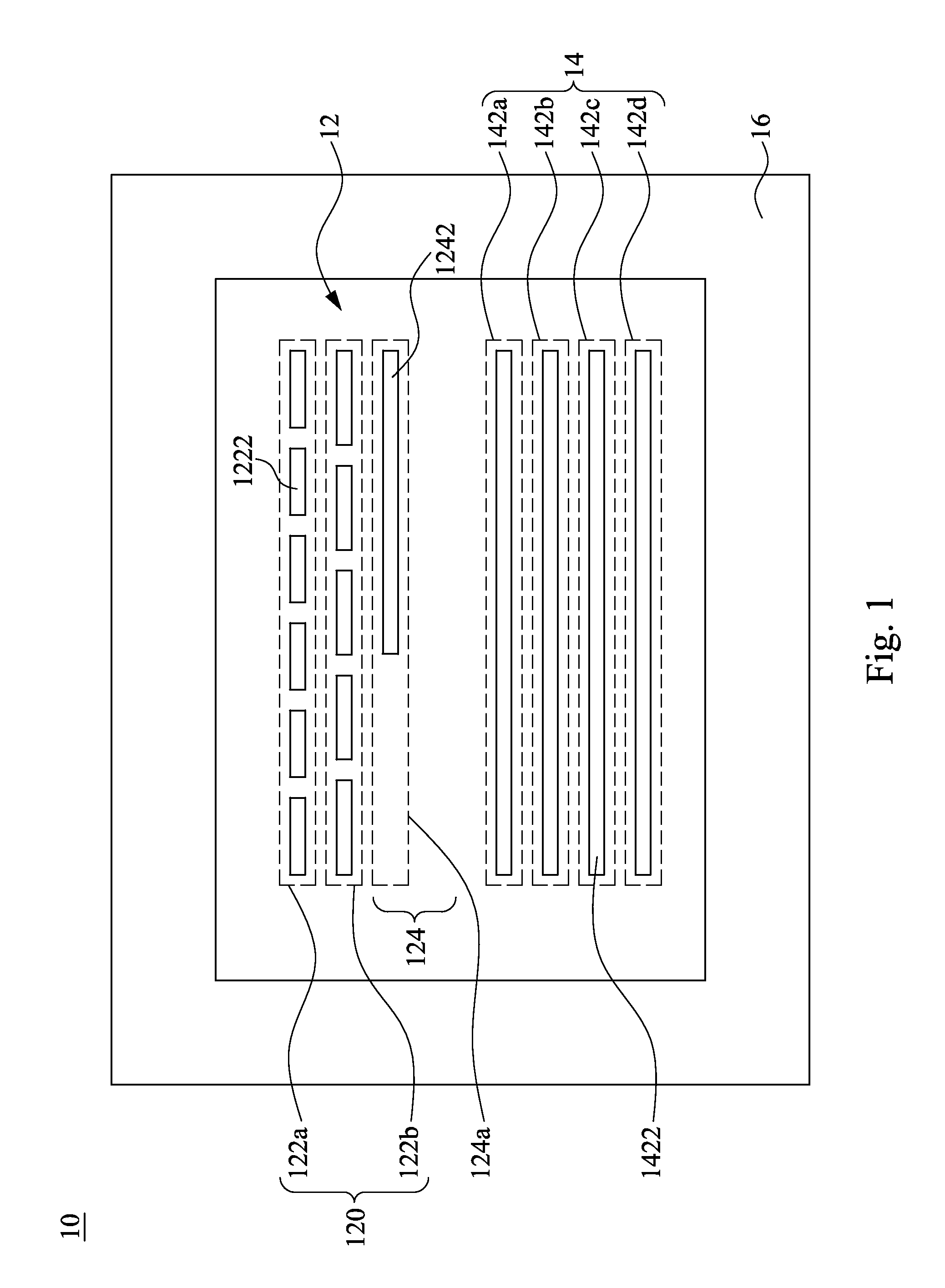
[0027]FIG. 1 illustrates a schematic block diagram of a transformer structure according to an embodiment of the present disclosure. A transformer 10 includes a primary winding unit 12, a secondary winding unit 14 and a magnetic core 16. The primary winding unit 12 includes an input primary winding part 120 and a shielding winding part 124, in which the input primary winding part 120 is connected to at least one switch component (e.g., switch component 104 as shown in FIG. 3). The input primary winding part 120 is electrically connected to the shielding winding part 124. The secondary winding unit 14 is inductively coupled to the primary winding unit 12. The primary winding unit 12 and the secondary winding un...


PUM

PropertyMeasurementUnit
diameteraaaaaaaaaa
magneticaaaaaaaaaa
transmissionaaaaaaaaaa

Abstract

A transformer includes a primary winding unit, a secondary winding unit and a magnetic core. The primary winding unit includes a first input primary winding part and a first shielding winding part. The first input primary winding part is electrically connected to at least one switch component, and the first input primary winding part is electrically connected to the first shielding winding part. The secondary winding unit is inductively coupled to the primary winding unit, and the first shielding part is disposed between the first input primary winding part and the secondary winding part. Then, the primary winding unit and the secondary winding unit are assembled to the magnetic core.

Description

RELATED APPLICATIONS[0001]This application claims priority to China Application Serial Number 201310198753. 3 filed May 24, 2013, which is herein incorporated by reference.BACKGROUND[0002]1. Technical Field[0003]The present disclosure relates to a transformer. More particularly, the present disclosure relates to a transformer with shielding winding.[0004]2. Description of Related Art[0005]A switching power supply conducts switching operations by a switch of the power converter to control the transmission of power. However, the switching operation of the switch may generate the electromagnetic noise, and that is, the operating power converter becomes a noise source for an electrical grid and surrounding equipments. To prevent the severe interference of the noise source, global governments and the related international organizations collectively constitute EMC (electromagnetic compatibility) specification.[0006]The electromagnetic noise includes common-mode and differential-mode noise...

Claims


Application Information

Patent Timeline
Patent Type & Authority Applications(United States)
IPC IPC(8): H01F27/36
CPCH01F27/362H01F27/289H01F27/24H01F27/2804H01F2027/2809
Inventor ZUO, ZHUANGZHOU, JIANJIAO, DE-ZHI
Owner DELTA ELECTRONICS INC
Why Eureka
Try Eureka