
Host/client system having a scalable serial bus interface

a serial bus and host/client technology, applied in the field of electrical circuits, can solve the problems the available space on the circuit board used therein, and the cost of providing pins for the address, control and data lines on the device packages, so as to achieve high bandwidth communication, the effect of increasing the number of pins

Inactive Publication Date: 2014-11-27
MONTEREY RES LLC
View PDF33 Cites 1 Cited by
  • Summary
  • Abstract
  • Description
  • Claims
  • Application Information

AI Technical Summary

Benefits of technology

The present invention relates to a system bridge and integrated interface for high-bandwidth communication between a CPU and a client. The system bridge is capable of scaling the data transfer rate, the number of channels, and the bus width through a scalable serial bus. This allows for control of the bus width between the host module and the client. The invention enables high-speed communication and efficient data transfer.

Problems solved by technology

As such embedded systems are continuously miniaturized to meet consumer demand, however, the available space on the circuit boards used therein as well as the cost to provide pins for the address, control and data lines on the device packages is becoming critically limited.
As a result of such space limitations, it has become difficult to enhance the performance of the clients without further widening the already wide buses between the host CPU and the clients.
Moreover, an increase in bus width would require an increase in the pin counts of the host CPU and clients, thereby increasing costs.
In addition, enhancing the performance of the clients by increasing data transfer rates between the host and the clients has also become difficult since the operation frequencies of conventional multi-drop bus interfaces are rapidly approaching their physical limits.

Method used


Image

  • Host/client system having a scalable serial bus interface
  • Host/client system having a scalable serial bus interface
  • Host/client system having a scalable serial bus interface

Examples


Embodiment Construction

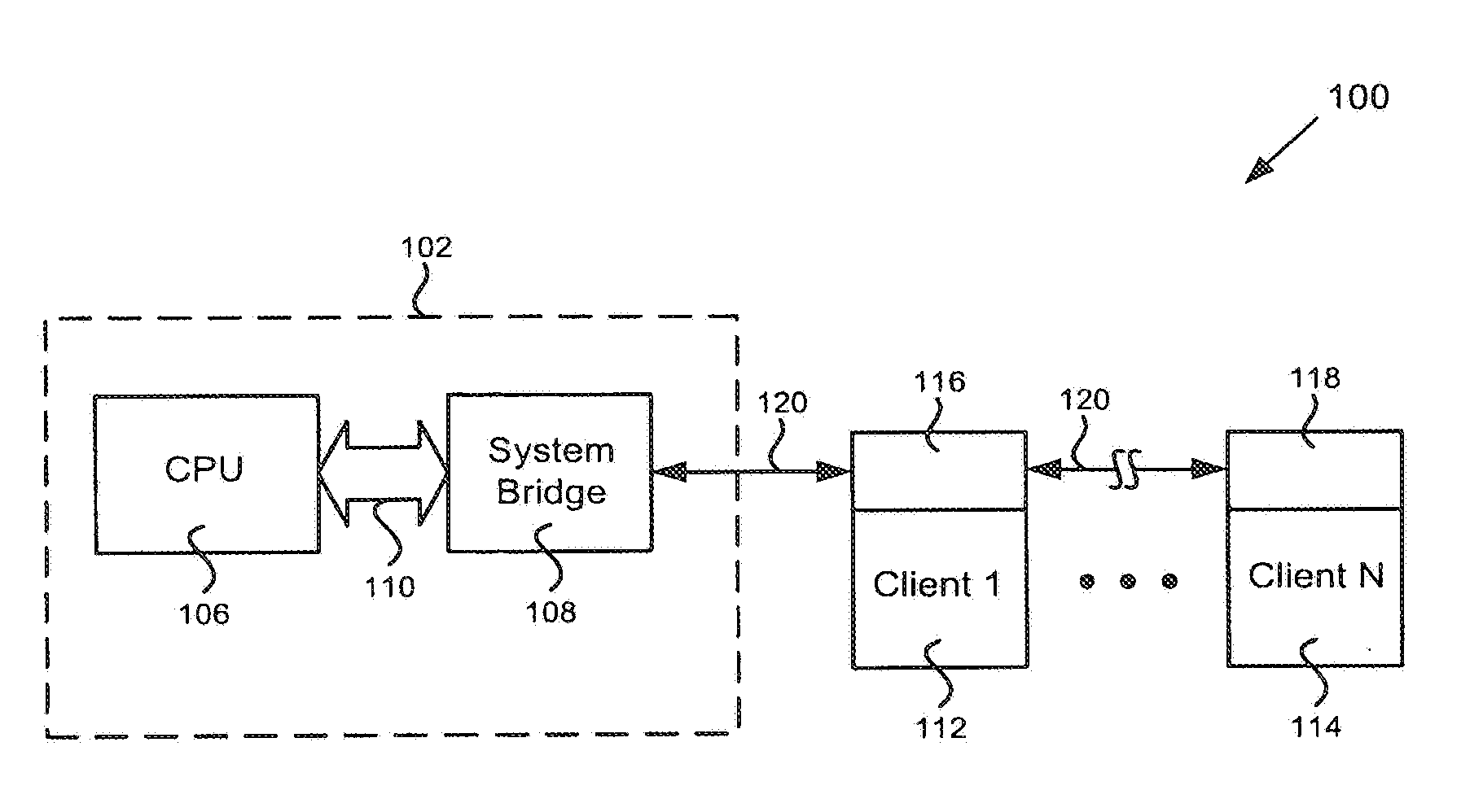
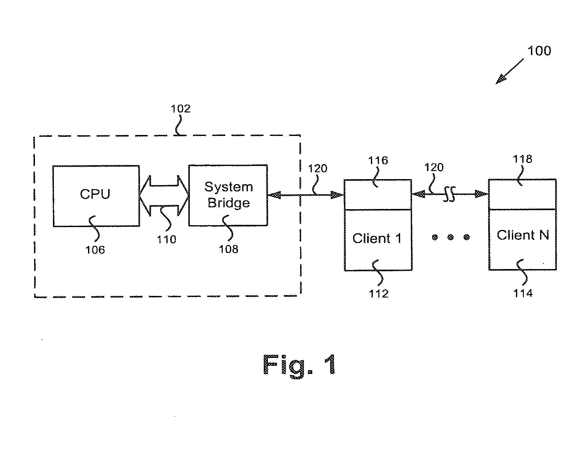
[0012]The present invention is directed to a host / client system having a scalable serial bus interface. The following description contains specific information pertaining to the implementation of the present invention. One skilled in the art will recognize that the present invention may be implemented in a manner different from that specifically discussed in the present application. Moreover, some of the specific details of the invention are not discussed in order not to obscure the invention.

[0013]The drawings in the present application and their accompanying detailed description are directed to merely exemplary embodiments of the invention. To maintain brevity, other embodiments of the present invention are not specifically described in the present application and are not specifically illustrated by the present drawings.

[0014]FIG. 1 shows a block diagram of an exemplary host / client system having a scalable serial bus interface in accordance with one embodiment of the present inven...


PUM


Abstract

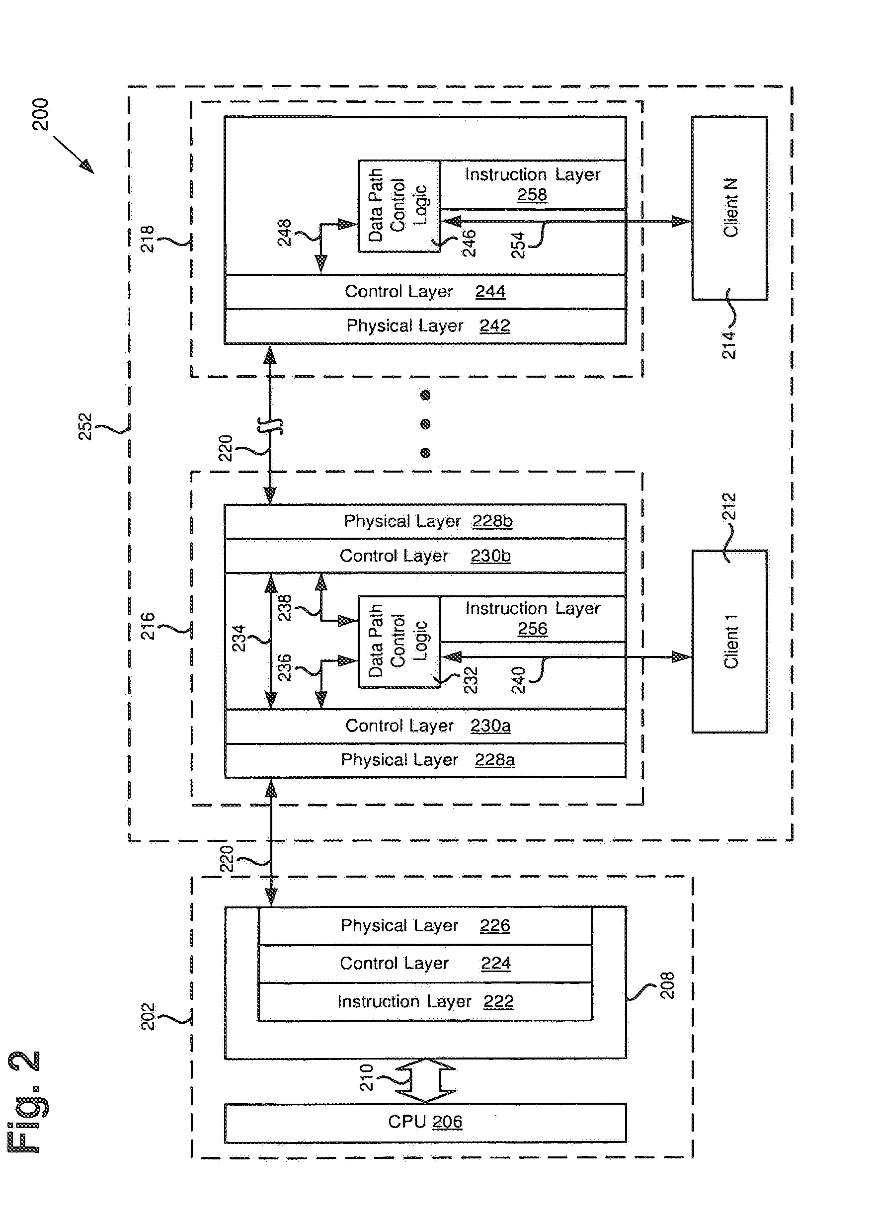
According to one exemplary embodiment, a system is provided. The system includes a system bridge, a host module including a central processing unit (CPU) coupled to the system bridge, a scalable serial bus coupled to the system bridge, a client controller coupled to the system bridge via the scalable serial bus, and first and second clients coupled to the client controller. The client controller is configured to interpret a communication received from the CPU and to provide the communication to the first client or to the second client based on a content of the communication. The scalable serial bus is configured such that each of the first and second clients have access to the scalable serial bus during respective time slots. The scalable serial bus is configured to scale at least one of a data transfer rate of the scalable serial bus, a number of channels on the scalable serial bus, or a bus width of the scalable serial bus.

Description

[0001]This application is related to U.S. Non-Provisional application Ser. No. 11 / 638,338, filed Dec. 12, 2006, which is incorporated by reference herein in its entirety.1. TECHNICAL FIELD[0002]The present invention is generally in the field of electronic circuits. More particularly, the present invention is in the field of bus interface design.2. BACKGROUND[0003]Modern embedded systems, such as mobile phones and other portable electronic devices, typically include a host CPU which communicates with various clients, such as volatile random access memory devices and nonvolatile random access memory devices, through conventional multi-drop bus interfaces. Such clients typically require many address and control lines, thus requiring wide buses between the host CPU and the clients, and may each require different interface and control circuitry.[0004]As such embedded systems are continuously miniaturized to meet consumer demand, however, the available space on the circuit boards used the...

Claims


Application Information

Patent Timeline
Patent Type & Authority Applications(United States)
IPC IPC(8): G06F13/16G06F13/362G06F13/42
CPCG06F13/1678G06F13/3625G06F13/4282G06F13/4247
Inventor ROSNER, STEPHANHASAN, QAMRULMAH, JEREMY
Owner MONTEREY RES LLC
Learn More