
Caseless Projectile and Launching System

Active Publication Date: 2014-12-04
BATTELLE MEMORIAL INST
View PDF14 Cites 16 Cited by
  • Summary
  • Abstract
  • Description
  • Claims
  • Application Information

AI Technical Summary

Benefits of technology

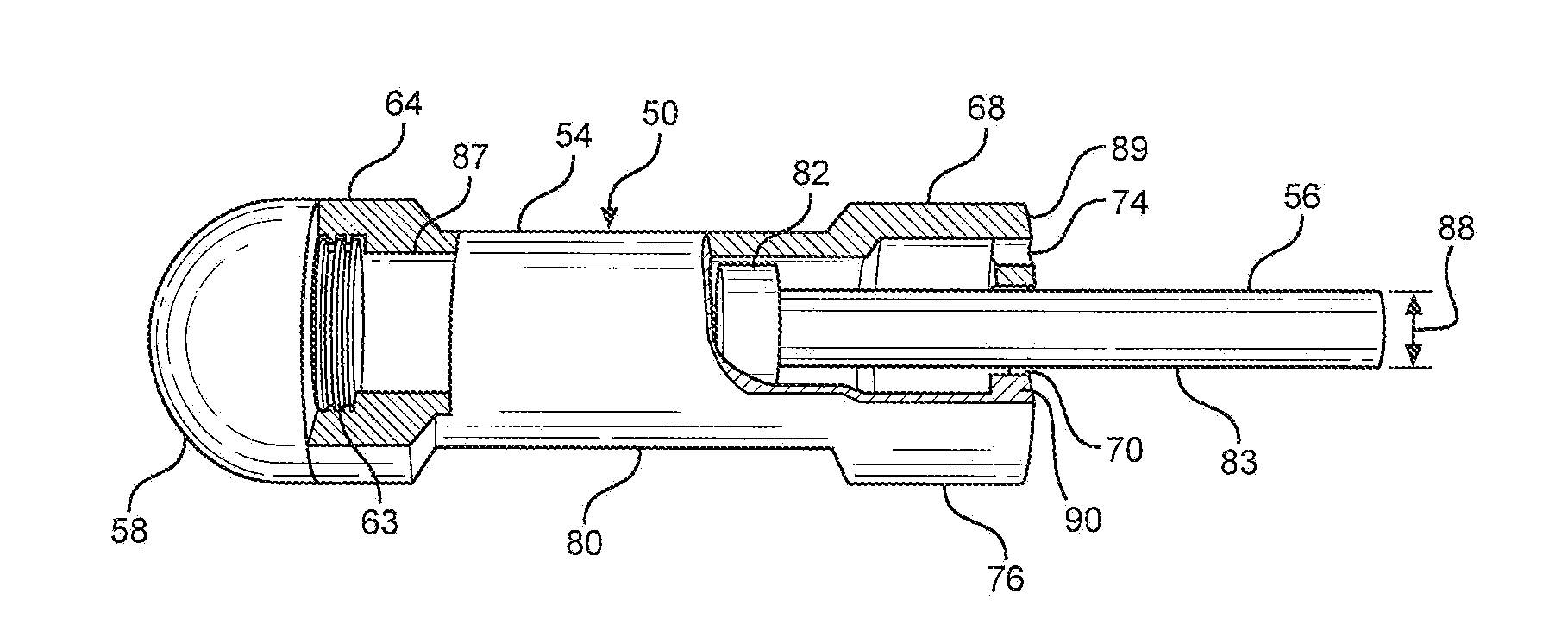
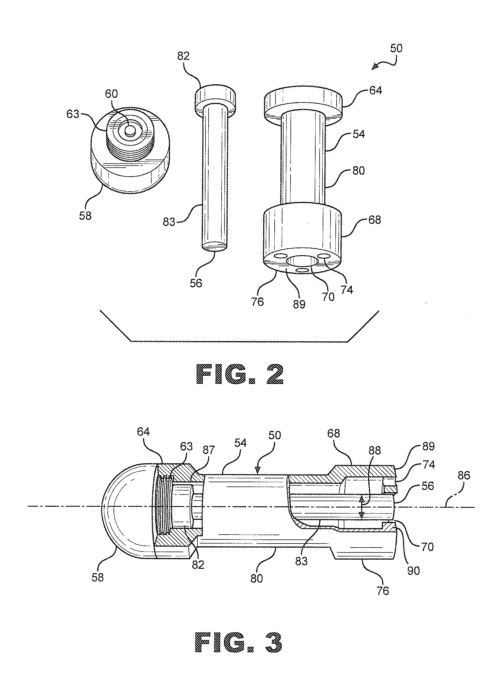
The invention provides a launcher with a sliding breech and an energy-absorbing plug. The locking pin prevents the breech face from moving when a projectile is launched, but the plug absorbs energy from the projectile to reduce the launch velocity when the locking pin is unlocked. This allows for greater control of the projectile's launch velocity.

Problems solved by technology

The disadvantage of such construction is that the barrel is extremely heavy and is not really suitable for light-weight non-lethal applications.
Typically, extra air bottles and a compressor to refill empty bottles are required for sustained operations and the whole arrangement tends to be relatively heavy, while requiring a high logistic burden.
Other non-lethal systems typically use a blunt, relatively large projectile that is cumbersome to transport and fire.
However, such arrangements typically lack accuracy and cannot be switched to lethal fire in an efficient manner.
However, they are often not capable of the same fire rate as the compressed air guns because the weapon has to be operated manually to reload for successive shots.
In general, solid propellant driven non-lethal ammunition lacks the energy to reliably operate an automatic or semi-automatic reloading mechanism of a weapon designed to fire high-pressure ammunition.
However, these known launchers employ projectiles which are both expensive and large, thereby requiring a large volume for ammunition storage and greatly reducing the readiness of the launcher for lethal applications.
In general, the use of non-lethal ammunition in weapons that are otherwise used to fire lethal ammunition compromises the safety of the user by decreasing the readiness to respond with lethal force when necessary.

Method used


Image

  • Caseless Projectile and Launching System
  • Caseless Projectile and Launching System
  • Caseless Projectile and Launching System

Examples


Embodiment Construction

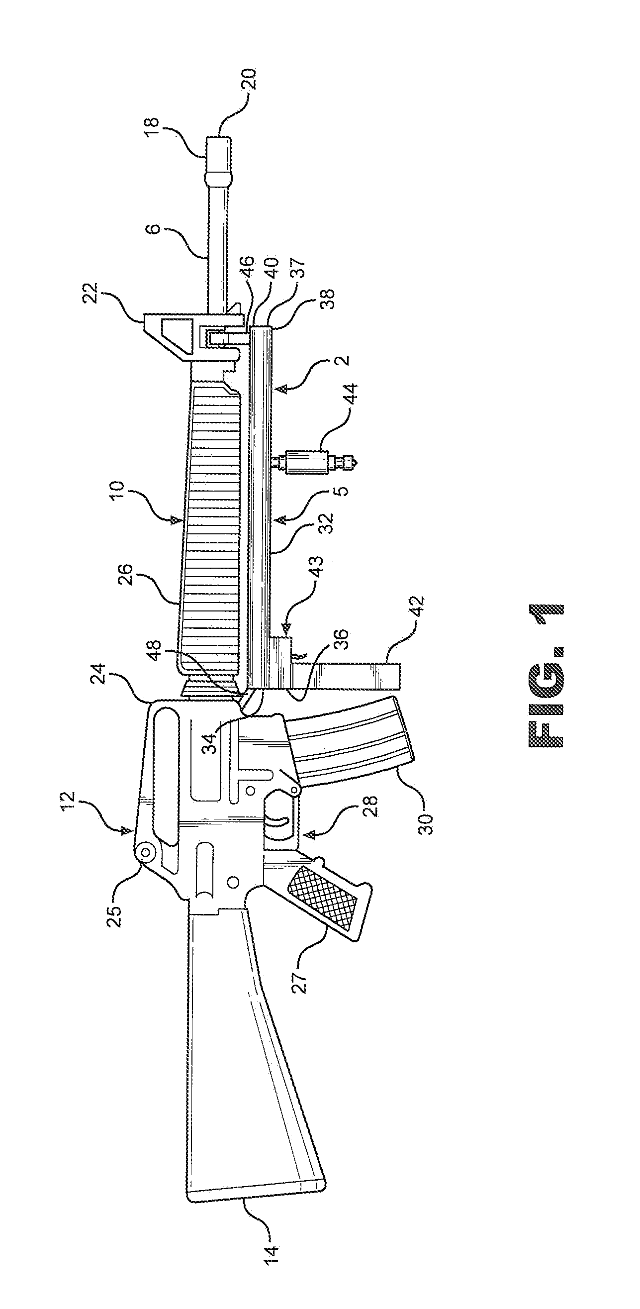
[0055]With initial reference to FIG. 1, there is shown a launching system 2 including a launcher 5 mounted under a barrel 6 of a rifle 10. However, launching system 2 can also be mounted to the side of barrel 6. Rifle 10 is preferably an M16 rifle or an M4 carbine equipped with Picatinny rails on the hand guards, but launching system 2 may be mounted to various types of military or civilian rifles. In any case, launching system 2 is preferably mounted so that it does not interfere with normal lethal operation of rifle 10 when fired or used with a bayonet (not shown).

[0056]As depicted, rifle 10 includes a central breech portion 12, a butt 14 extending rearward from breech portion 12 and a barrel 6 extending forwardly from central breech portion 12. Barrel 6 is provided with a flash arrester 18 mounted at its forward end 20. A forward sight 22 is mounted on barrel 6 and set back from forward end 20. A transport handle 24 includes a rear sight 25 and is mounted on central breech portio...


PUM


Abstract

A launcher system includes a launcher having a barrel adapted to receive a projectile and a charge of propellant and a velocity variator configured to shift relative to barrel to selectively vary a launch velocity of projectile from launcher. The velocity variator may be constituted by a collar selectively controlling the propellant gases vented out of projectile and into barrel and / or a sliding breech face behind which is an energy-absorbing plug.

Description

BACKGROUND OF THE INVENTION[0001]1. Field of the Invention[0002]The present invention pertains to the field of weaponry and, more particularly, to a caseless projectile and an associated launching system used for both non-lethal and lethal applications.[0003]2. Discussion of the Prior Art[0004]In general, most firearms or weapons have employed bullets, which are typically fired through a relatively heavy barrel. Usually a cartridge including a bullet, a casing and smokeless propellant located in the casing is employed. Conventional hand carried weapons are typically fired by pulling a trigger which allows a movable firing pin to impact the aft end of the bullet cartridge to initiate a primer and ignite the smokeless propellant located in the bullet cartridge such that the bullet is fired out the barrel. When the firearm is fired, the bullet will have an initial high acceleration caused by high temperature and pressure of gases that propel the bullet through the barrel. Typically, th...

Claims


Application Information

Patent Timeline
IPC IPC(8): F41A1/06F41A9/61F42B5/18F42B15/00F41A3/12F41A21/00
CPCF41A1/06F41A3/12F41A9/61F42B5/18F42B15/00F41A21/00F41A21/28F42B5/184F42B15/10
Inventor WIDDER, JEFFREY M.PERHALA, CHRISTOPHER A.RASCOE, JAMES R.
Owner BATTELLE MEMORIAL INST
Learn More