Multiaxial micro-electronic inertial sensor

a multi-axial, micro-electronic technology, applied in the direction of acceleration measurement using interia force, speed measurement using gyroscopic effects, electric/magnetic means, etc., to achieve the effect of easy control of geometric design

Inactive Publication Date: 2014-12-04
TRONICS MICROSYST
View PDF8 Cites 33 Cited by
  • Summary
  • Abstract
  • Description
  • Claims
  • Application Information

AI Technical Summary

Benefits of technology

[0016]It is an object of the invention to provide a micro-electromechanical system (MEMS) device for multiaxis acceleration and rotation detection. More specifically, the invention aims at an easily controllable geometric design of the proof

Problems solved by technology

However, this does not necessarily mean

Method used


Image

  • Multiaxial micro-electronic inertial sensor
  • Multiaxial micro-electronic inertial sensor
  • Multiaxial micro-electronic inertial sensor

Examples


Embodiment Construction

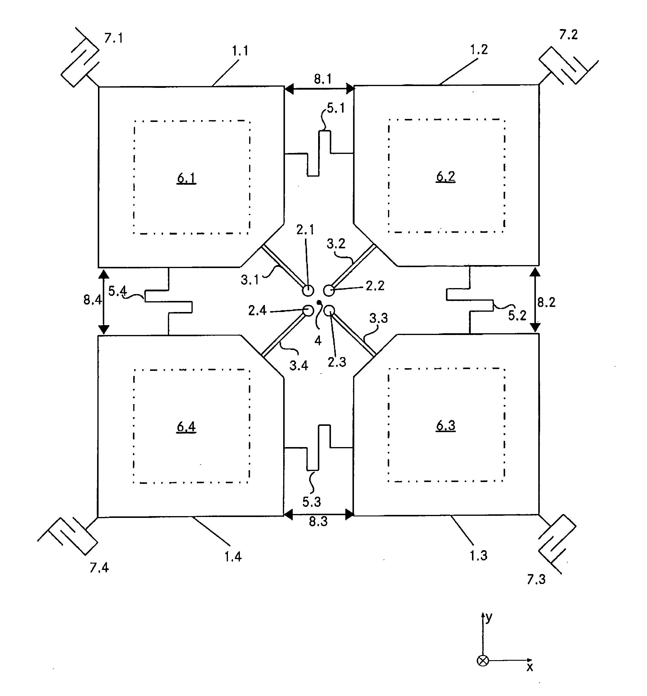
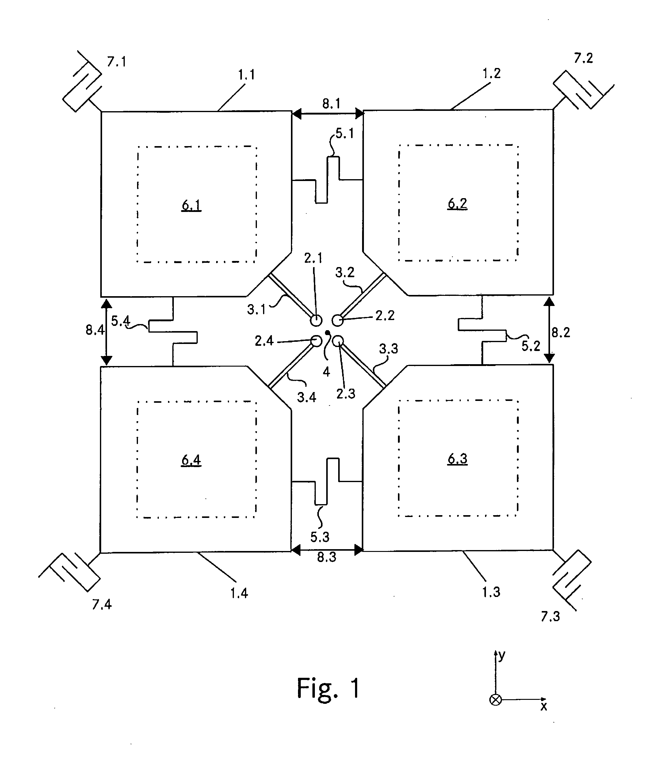
[0096]FIG. 1 is a very rough geometric diagram of a first embodiment that serves to illustrate the basic principle and the functional elements that may be used in the scope of the invention.

[0097]There are four proof-mass elements 1.1, . . . , 1.4, which may have a shape that is more or less a square. The four proof-mass elements 1.1, . . . , 1.4 together define the proof-mass system. Each one of the proof-mass elements 1.1, . . . , 1.4 is directly connected to an anchor structure. In the present embodiment, the anchor structure comprises four anchor posts 2.1, . . . , 2.4 placed close to the centre of the proof-mass system. The anchor posts 2.1, . . . , 2.4 rise from the substrate (below the proof-mass elements 1.1, . . . , 1.4) to the level of the proof-mass system. Each of the proof-mass elements 1.1, . . . , 1.4 is connected to its anchor element 2.1, . . . , 2.4 by means of a suspension element 3.1, . . . , 3.4. According to the embodiment of FIG. 1 the suspension elements may ...


PUM


Abstract

A resonator micro-electronic inertial sensor, preferably a micro-electromechanical system (MEMS) sensor (e.g. a gyro), for detecting linear accelerations and rotation rates in more than one axis comprises: a proof-mass system (21.1, 21.4) flexibly suspended above a substrate for performing a rotational in-plane vibration about a central axis (24,) a drive electrode system (D1, . . . D4) for driving the proof-mass system (21.1, . . . 21.4) to perform said rotational in-plane vibration, and a sensing electrode system (S1, S8) connected to the proof-mass system (21.1, . . . 21.4) for detecting linear accelerations or rotation rates in more than one axis. Said proof-mass system (21.1 21.4) has more than two proof-mass elements flexibly coupled (25.1a, 25.1b) to each other. Each proof-mass element (21.1, 21.2) is directly and flexibly connected (23.1, 25.1a, 25.1b) to an anchor structure (22) on the substrate (32). The proof-mass elements (21.1, . . . 21.4) are preferably arranged In a ring-shaped configuration between an inner and an outer radius (R1, R2) with respect to the central axis (24).

Description

TECHNICAL FIELD[0001]The invention refers to a resonator micro-electronic inertial sensor, preferably a micro-electromechanical system (MEMS) sensor (for instance a gyro), for detecting linear accelerations and rotation rates in more than one axis comprising:[0002]a) a proof-mass system flexibly suspended above a substrate for performing a rotational in-plane vibration about a central axis,[0003]b) wherein said proof-mass system has more than two proof-mass elements flexibly coupled to each other,[0004]c) a drive electrode system for driving the proof-mass system to perform said rotational in-plane vibration,[0005]d) a sensing electrode system connected to the proof-mass system for detecting linear accelerations or rotation rates in more than one axis.[0006]The invention also relates to a method for detecting linear accelerations and rotation rates by such a device.BACKGROUND, PRIOR ART[0007]The concept of detecting accelerations or rotation rates in more than one axis has been know...

Claims


Application Information

Patent Timeline
IPC IPC(8): G01P15/18G01P15/08G01C19/5712
CPCG01P15/18G01P2015/0862G01P15/08G01C19/5712G01P15/14G01P15/125
Inventor LECLERC, JACQUES
Owner TRONICS MICROSYST
Why Eureka
Try Eureka