Flash tank with flared inlet insert and method for introducing flow into a flash tank

a flash tank and flow technology, applied in the field of flash tanks, can solve problems such as turbulent flow of liquor into the flash tank

Active Publication Date: 2014-12-04
ANDRITZ INC
View PDF26 Cites 6 Cited by
  • Summary
  • Abstract
  • Description
  • Claims
  • Application Information

AI Technical Summary

Problems solved by technology

The transition from the inlet pipe to the flash tank is abrupt, which causes disruption and turbulence in the liquor flowing into the flash tank.

Method used


Image

  • Flash tank with flared inlet insert and method for introducing flow into a flash tank
  • Flash tank with flared inlet insert and method for introducing flow into a flash tank
  • Flash tank with flared inlet insert and method for introducing flow into a flash tank

Examples


Embodiment Construction

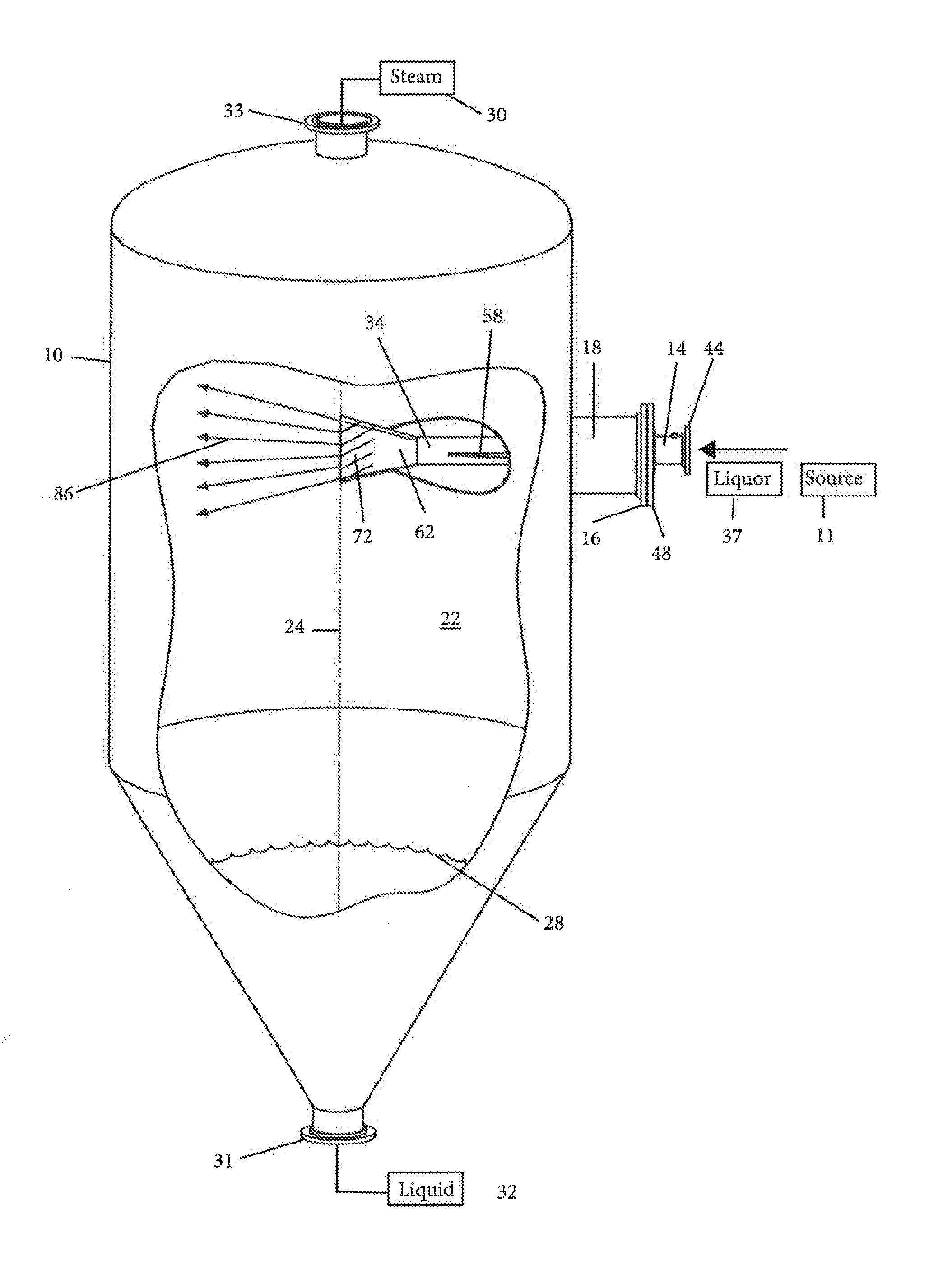
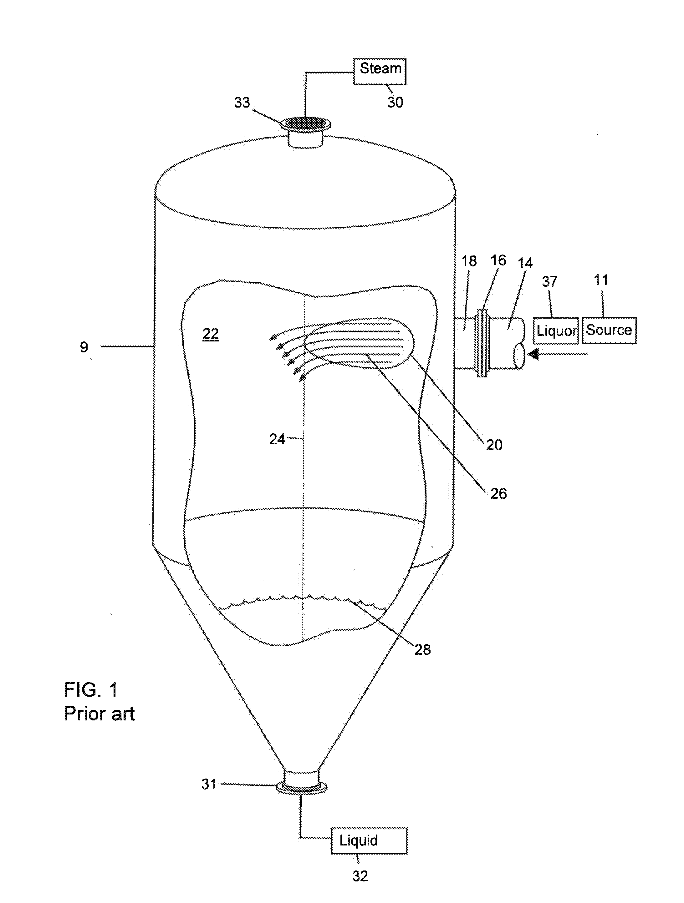
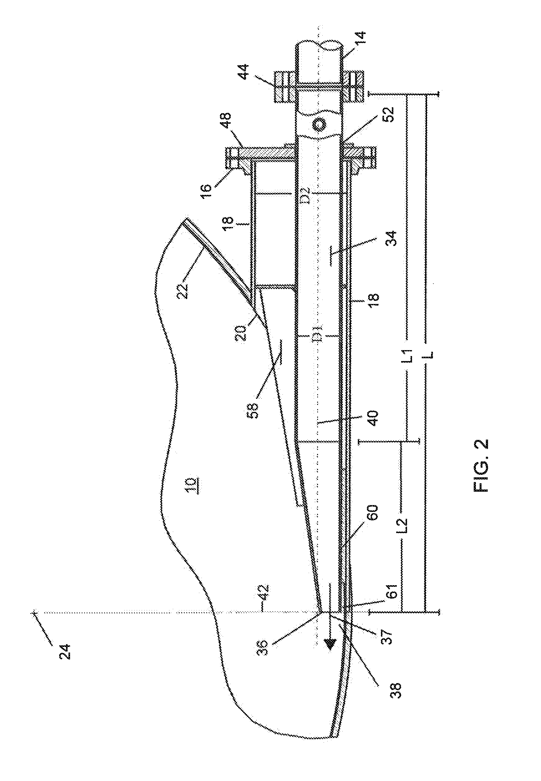
[0023]FIG. 1 is a schematic diagram of a conventional flash tank 9 coupled to a source 11 of black liquor 37. The source 11 of black liquor 37 may be a header 14, e.g., a cylindrical header or a mixing spool that receives and combines black liquor 37 from multiple streams into a single stream 26 that enters the flash tank 9, but the black liquor 37 may also be extracted from a pressurized batch or continuous digester vessel in a Kraft cooking process for producing pulp. The header 14 may have an internal passage (see FIG. 2) for the black liquor 37 having a circular cross-section.

[0024]The black liquor flows 37 from the header 14 through a flanged coupling 16 into an inlet port 18. As the black liquor 37 exits the inlet port 18 through a conventional outlet 20, the black liquor 37 becomes a stream 26 of black liquor 37. The transition from the conventional outlet 20 to the inside sidewall surface 22 of the flash tank 9 is abrupt. Disruption and turbulence can occur as the stream 26 ...


PUM

PropertyMeasurementUnit
temperaturesaaaaaaaaaa
pressuresaaaaaaaaaa

Abstract

A flash tank including: an interior chamber having a interior surface formed by a sidewall of the flash tank; a vapor exhaust port coupled to an upper portion of the chamber; a liquid discharge port coupled to a lower portion of the chamber; an insert inlet tube having an insert outlet and inserted into an inlet port of the chamber, wherein the insert inlet tube extends inward of the sidewall and the insert outlet has an elongated cross-sectional shape oriented substantially parallel to a center vertical axis of the flash tank and substantially perpendicular to a radial line of the flash tank, such that the insert outlet is substantially tangential to the sidewall.

Description

RELATED APPLICATION[0001]This application claims the benefit of priority to U.S. App. No. 61 / 827,830, filed on May 28, 2013, the entire contents of which are incorporated herein by reference pursuant to 35 U.S.C. §119(e).TECHNICAL FIELD[0002]The present disclosure relates generally to flashing fluids extracted from pressurized reactor vessels and particularly to flash tanks for flashing black liquor from a pressurized reactor vessel in a pulping or biomass treatment system.BACKGROUND OF THE INVENTION[0003]Flash tanks are generally used to flash a high pressure fluid liquor stream including steam and condensate. A flash tank typically has a high pressure inlet port, an interior chamber, an upper steam or gas discharge port and a lower condensate or liquid discharge port. Flash tanks safely and efficiently reduce pressure in a pressurized fluid stream, allow recovery of heat energy from the vapors produced by the stream, and collect chemicals from the condensate of the stream.[0004]Fl...

Claims


Application Information

Patent Timeline
Patent Type & Authority Applications(United States)
IPC IPC(8): D21C11/00
CPCD21C11/00D21C11/04D21C11/06D21C11/10B01D19/0036
Inventor GROGAN, RICHARD M.NELLIS, WALTER EDWARDHUNT, TYSON BRADFORD
Owner ANDRITZ INC
Why Eureka
Try Eureka