Electric power tool

a technology of electric power tools and power tools, applied in the direction of manufacturing tools, power tools, power tools, etc., can solve problems such as cumbersome operation, and achieve the effect of reducing the operation of the operator

Active Publication Date: 2014-12-04
HITACHI KOKI CO LTD
View PDF20 Cites 27 Cited by
  • Summary
  • Abstract
  • Description
  • Claims
  • Application Information

AI Technical Summary

Benefits of technology

[0015]According to the present invention, the rotating speed of the electric motor is automatically controlled in accordance with the load of the tip tool. Therefore, it is possible to reduce operations of an operator by this electric power tool.

Problems solved by technology

However, in the electric power tool described in Patent document 1, the operator has to operate the speed changing dial so as to change the rotating speed of the electric motor in accordance with the load of that tip tool, that is, the type of that tip tool and the type of that operation, and it is cumbersome to operate it.

Method used


Image

  • Electric power tool
  • Electric power tool
  • Electric power tool

Examples


first embodiment

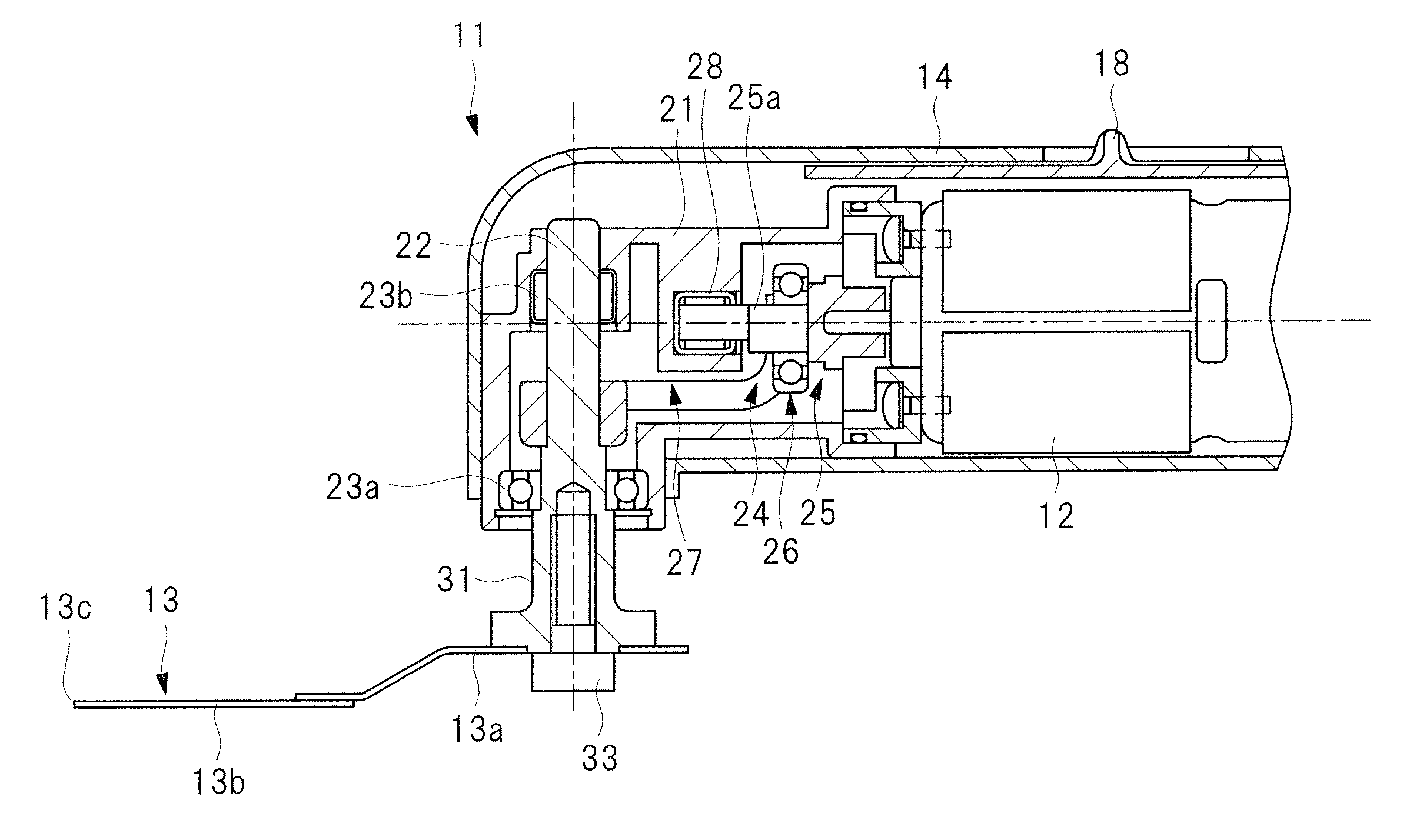
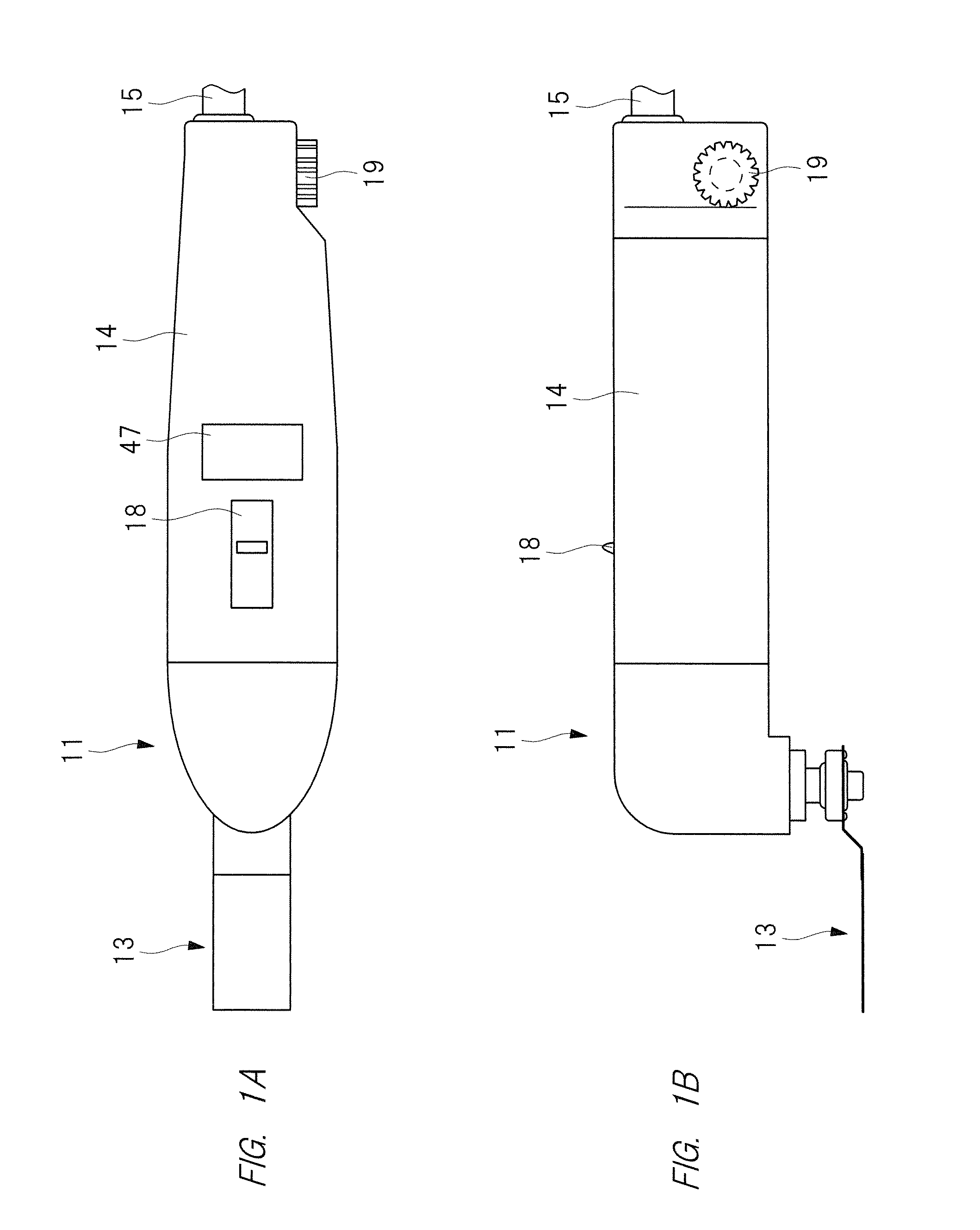
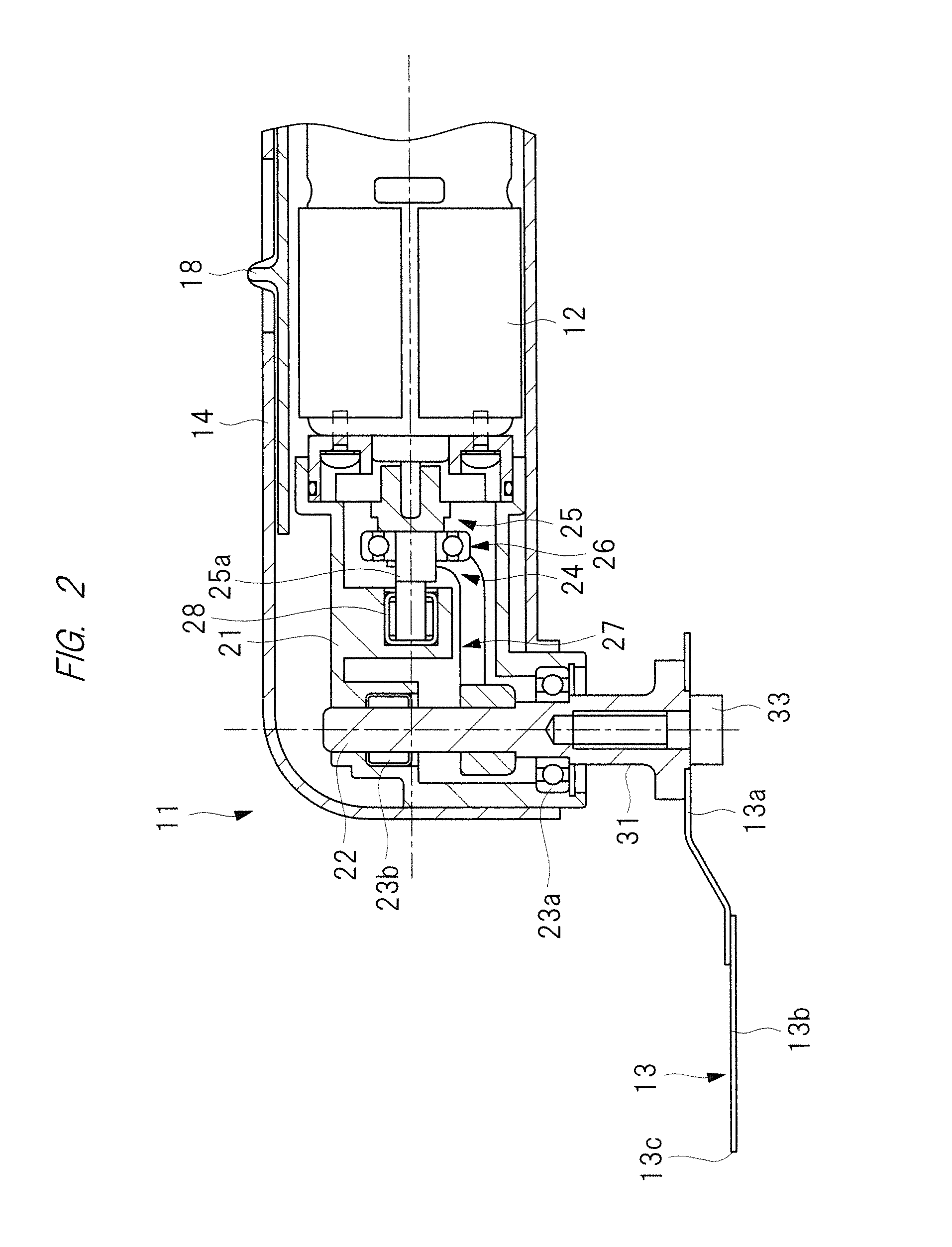
[0046]Hereinafter, the present invention will be explained in detail with reference to the drawings. An electric power tool 11 shown in FIGS. 1 and 2 is a power tool using an electric motor 12 as a drive power source. Various operations can be selectively carried out with the electric power tool 11 by changing a tip tool attached thereto. For example, if a tip tool provided with saw teeth is attached to the electric power tool 11, the electric power tool 11 can carry out an operation of cutting an object with the tip tool. If a tip tool to which a diamond chip, a carbide chip, or the like is fixed is attached to the electric power tool 11, the electric power tool 11 can carry out an operation of grinding or polishing an object with the tip tool. Furthermore, if a scraper-shaped tip tool is attached to the electric power tool 11, an operation of peeling off an object from a body can be carried out with the tip tool. The electric power tool 11 shown in FIGS. 1 and 2 is an example in w...

second embodiment

[0106]Next, detecting the load state of the electric motor, which is provided in the electric power tool of the present invention, with high precision will be explained with reference to the drawings.

[0107]Hereinafter, the second embodiment will be explained in detail.

[0108]

[0109]FIGS. 12A and 12B are external views showing an example of an electric power tool according to the second embodiment. FIG. 13 is a sectional view of the electric power tool of FIGS. 12A and 12B.

[0110]An electric power tool 110 is a power tool using an electric motor 114 as a drive power source. With the electric power tool 110, various operations can be selectively carried out by changing a tip tool attached. In other words, a plurality of tip tools can be selectively attached and detachable from the electric power tool 110.

[0111]For example, when a tip tool provided with saw teeth is attached to the electric power tool 110, the electric power tool 110 can carry out an operation of cutting an object with th...

third embodiment

[0175]Next, the electric power tool 110 shown in FIG. 12 and FIG. 13 will be explained.

[0176]

[0177]The above-described second embodiment employs the configuration in which the load state of the electric motor 114 is detected on the basis of the conduction angle of the triac 157. However, in the third embodiment, a technique in which the load state of the electric motor 114 is detected on the basis of the value indicative of the current flowing to the electric motor 114 instead of the conduction angle of the triac 157.

[0178]In this case, the control part 54 executes a second automatic switching process. The second automatic switching process is a process of judging whether the electric motor 114 is in the load state or in the no-load state on the basis of the value indicative of the current flowing to the electric motor 114, and on the basis of this judgment, switching a mode of controlling the rotating speed of the electric motor 114 to the no-load mode or the load mode.

[0179]Since ...


PUM


Abstract

An object of the present invention is to provide an electric power tool capable of automatically changing the rotating speed of an electric motor in accordance with operation conditions. The electric power tool 11 which carries out an operation of polishing, peel-off, cutting, or the like by swinging a tip tool 13 attached to a tool retaining part 31 within the range of predetermined angles by the drive power of the electric motor 12, wherein the electric power tool has a control device configured to indirectly detect the load of the tip tool from a current value, and to control the rotating speed of the electric motor 12 to a maximum rotating speed and a minimum rotating speed on the basis of the load of the tip tool 13.

Description

CROSS-REFERENCE TO RELATED APPLICATION[0001]The present application claims priority from Japanese Patent Applications Nos. 2013-116223 filed on May 31, 2013 and 2013-157001 filed on Jul. 29, 2013, the content of which is hereby incorporated by reference into this application.TECHNICAL FIELD OF THE INVENTION[0002]The present invention relates to an electric power tool which carries out an operation by reciprocating a tip tool by an electric motor.BACKGROUND OF THE INVENTION[0003]An example of an electric power tool, which can carry out a variety of operations including an operation of cutting an object, an operation of polishing an object, and an operation of peeling off an object by transmitting the drive power of an electric motor to a tip tool, is described in Japanese Patent Application Laid-Open Publication No. 2012-232381 (hereinafter simply refer to as “Patent Document 1”). The electric power tool described in Patent Document 1 has: an electric motor provided in a tool main bo...

Claims


Application Information

Patent Timeline
Patent Type & Authority Applications(United States)
IPC IPC(8): B23Q15/007B23Q5/027B25F5/00
CPCB23Q15/0075B23Q5/027B25F5/00H02P7/245
Inventor MATSUNAGA, KENICHIKAWANO, YOSHIKAZU
Owner HITACHI KOKI CO LTD
Why Eureka
Try Eureka