Wireless power transmitting device and method for controlling to transmit wireless power signal in wireless power transmitting device

a wireless power transmission and wireless power technology, applied in the direction of exchanging data chargers, inductances, transportation and packaging, etc., can solve the problems of instantaneous discharging, degrading the lifespan of the battery pack and its performance, and reducing the reception so as to increase the reliability of power control in wireless power transmission and reduce the error rate of the wireless power receiving signal

Active Publication Date: 2014-12-04
GE HYBRID TECH
View PDF1 Cites 14 Cited by
  • Summary
  • Abstract
  • Description
  • Claims
  • Application Information

AI Technical Summary

Benefits of technology

[0028]According to the embodiment of the present invention having the aforementioned configuration, since wireless power receiving information is obtained by receiving a wireless power receiving signal obtained through at least two sensors and by processing the received signal, it is possible to increase reliability of power control in wireless power transmission.
[0029]Further, since a reception error is generated only when all signals obtained from at least two sensors are in an error state, a reception error rate of the wireless power receiving signal is reduced, so that it is possible to guarantee continuity of the power control.

Problems solved by technology

However, if the power is supplied in the terminal supplying method, when the charger and the battery pack are combined with each other or are separated from each other, since terminals of both sides (a terminal of the battery pack and a terminal of the charger) have different potentials from each other, there is a problem that instantaneous discharging is caused.
Additionally, there is a concern that when foreign substances are present in the terminals of the both sides due to the instantaneous discharging, fire may occur.
Further, the electric energy charged in the battery pack is naturally discharged to the outside through the terminal of the battery pack due to moisture, so that a lifespan of the battery pack and performance thereof may be degraded.

Method used


Image

  • Wireless power transmitting device and method for controlling to transmit wireless power signal in wireless power transmitting device
  • Wireless power transmitting device and method for controlling to transmit wireless power signal in wireless power transmitting device
  • Wireless power transmitting device and method for controlling to transmit wireless power signal in wireless power transmitting device

Examples


Embodiment Construction

[0033]Hereinafter, a wireless power transmitting device and a method for controlling transmission of a wireless power signal in the wireless power transmitting device will be described in more detail with reference to the drawings.

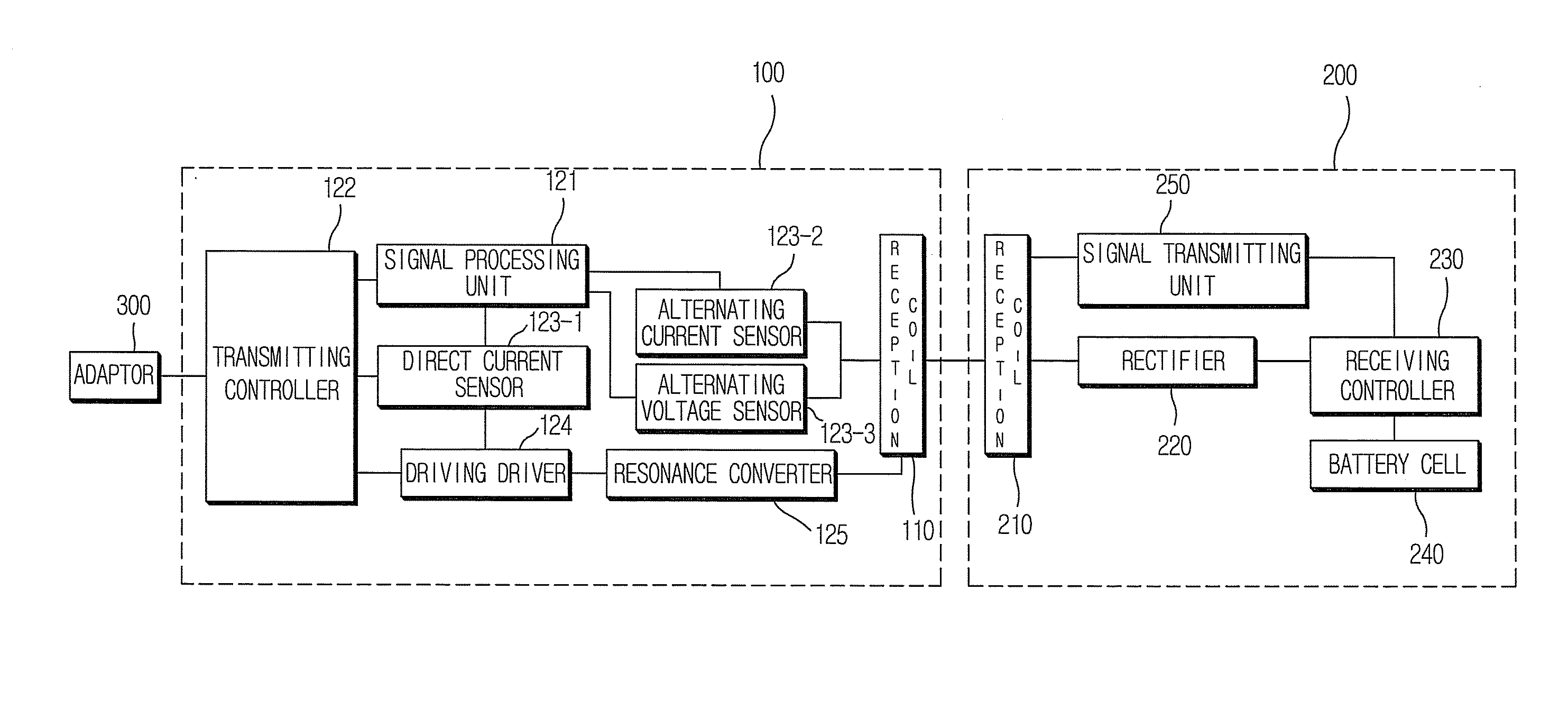
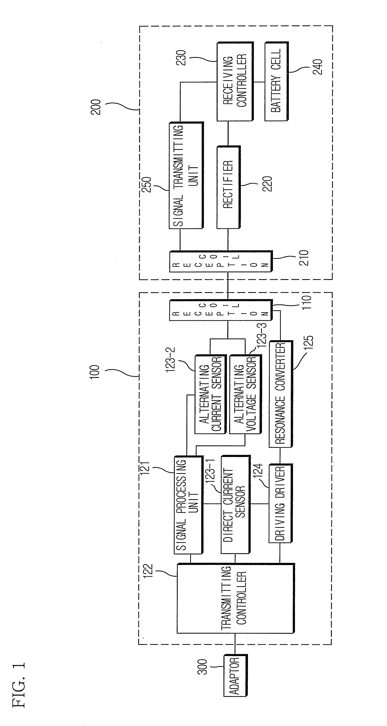
[0034]FIG. 1 is a block diagram of a wireless power transmitting system according to an embodiment of the present invention. As shown in the drawing, the wireless power transmitting system according to the embodiment of the present invention includes a wireless power transmitting device 100, a wireless power receiving device 200, and an adaptor 300. An external alternating current power of 110 V or 220 V is converted into a direct current power by the adaptor to be supplied to the wireless power transmitting device 100. Thereafter, when the wireless power transmitting device 100 transmits a wireless power signal to the wireless power receiving device 200 in an electromagnetic induction manner, the wireless power receiving device 200 that has received the p...


PUM


Abstract

There is provided a wireless power transmitting device including a transmission coil configured to transmit a wireless power signal to a wireless power receiving device; a driving driver configured to generate a wireless power driving signal which is a driving signal for the wireless power signal; an alternating current sensor configured to detect an alternating current signal of the transmission coil which is generated by a wireless power receiving signal including wireless power receiving information of a wireless power receiving device; an alternating voltage sensor configured to detect an alternating voltage signal of the transmission coil, the alternating current signal being generated by the wireless power receiving signal from the wireless power receiving device; a signal processing unit configured to process the alternating current signal and the alternating voltage signal from the alternating current sensor and the alternating voltage sensor; and a wireless power transmitting controller that, when the alternating current signal and the alternating voltage signal of the transmission coil are detected and signal processing is normally performed on at least one of the alternating current signal and the alternating voltage signal, obtains the wireless power receiving information through the signal on which the signal processing is performed and controls the driving driver on the basis of the wireless power receiving information. Further, there is provided a method for controlling to transmit a wireless power signal in the wireless power transmitting device.

Description

CROSS-REFERENCE TO RELATED APPLICATIONS[0001]This application is a national stage of International Application No. PCT / KR2012 / 011324, filed Dec. 21, 2012, which claims priority to U.S. Provisional Application No. 61 / 579,225, filed Dec. 22, 2011. All disclosures of the documents named above are incorporated herein by reference.BACKGROUND OF THE INVENTION[0002]1. Field of the Invention[0003]The present invention relates to a wireless power transmitting device that increases wireless power transmitting efficiency by more reliably detecting a signal from a wireless power receiving device, and a method for controlling transmission of a wireless power signal in the wireless power transmitting device.[0004]2. Description of the Related Art[0005]In general, a battery pack is configured to receive a power (electric energy) from an external charger to supply a power for operating a mobile terminal (a cellular phone or PDA) in a charged state, and includes a battery cell that is charged with t...

Claims


Application Information

Patent Timeline
Patent Type & Authority Applications(United States)
IPC IPC(8): H02J17/00H02J7/02
CPCH02J7/025H02J17/00H04B5/0037H04B5/0075H02J7/00034H02J50/12H02J50/80H02J50/90H02J50/40H02J50/60
Inventor JUNG, CHUN-KIL
Owner GE HYBRID TECH
Why Eureka
Try Eureka