Slotted waveguide antenna for near-field focalization of electromagnetic radiation

a waveguide antenna and electromagnetic radiation technology, applied in the direction of slot antennas, antennas, basic electric elements, etc., can solve the problems of pulsed signal degradation, limiting the application of electromagnetic and acoustic waves beams and pulses, diffraction and dispersion

Active Publication Date: 2014-12-04
SELEX ES
View PDF24 Cites 21 Cited by
  • Summary
  • Abstract
  • Description
  • Claims
  • Application Information

AI Technical Summary

Benefits of technology

[0011]The aim of the present invention is to provide a slotted waveguide antenna that will be able to overcome the drawbacks of the known art, and in particular an antenna for generating non-diffractive waves that can be applied in the microwave field.

Problems solved by technology

As is known, diffraction and dispersion are phenomena that limit the applications of beams and pulses of electromagnetic and acoustic waves.
Consequently, a pulsed signal may undergo degradation due to a temporal widening of its spectrum, which is undesirable.
The dispersion is hence a further limiting factor when there is the need for a pulse to maintain its own spectral characteristics, in particular its width over time, such as, for example, in communications systems.
These radiating structures are, consequently, costly and cumbersome to produce.

Method used


Image

  • Slotted waveguide antenna for near-field focalization of electromagnetic radiation
  • Slotted waveguide antenna for near-field focalization of electromagnetic radiation
  • Slotted waveguide antenna for near-field focalization of electromagnetic radiation

Examples


Embodiment Construction

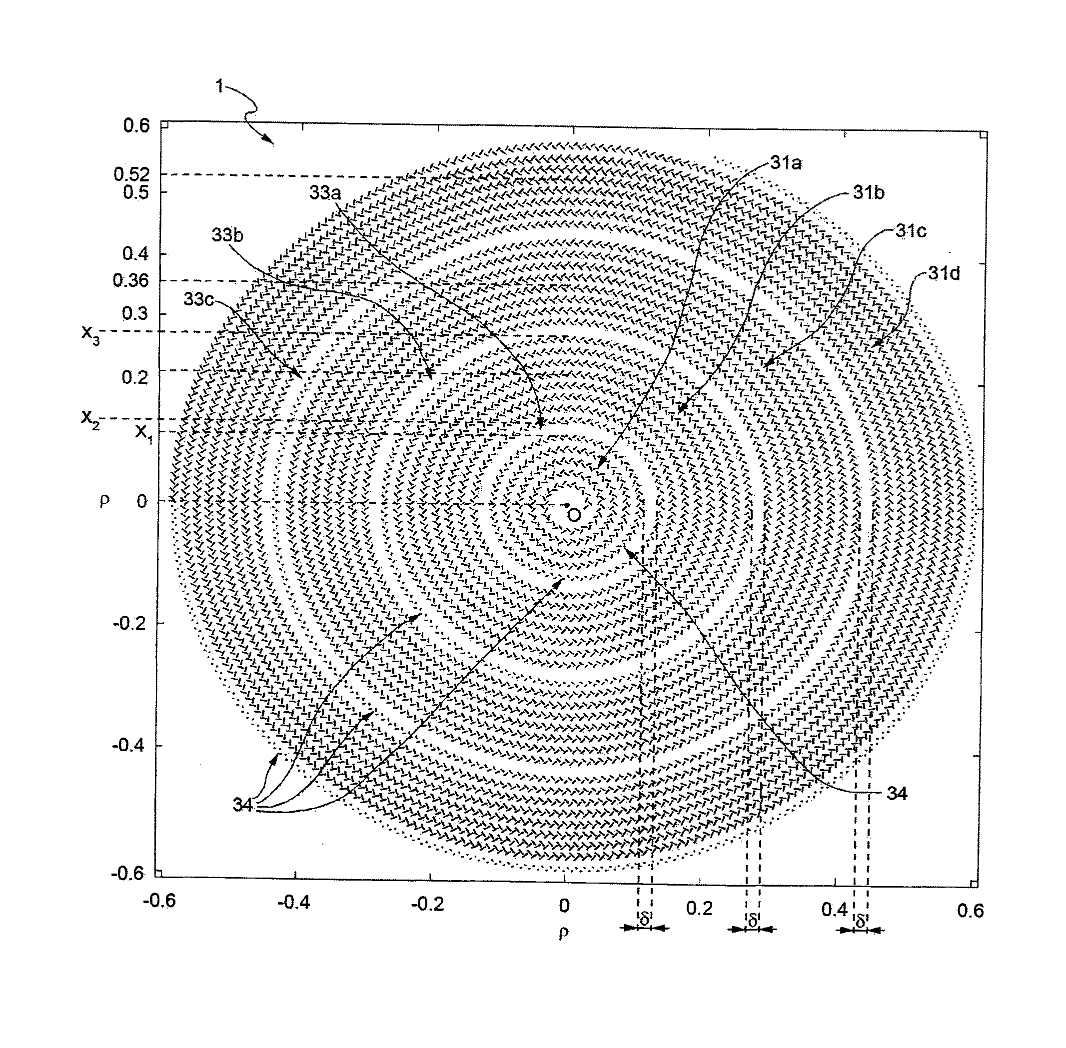
[0033]According to the present invention, a slot antenna is provided formed, as described in detail hereinafter, by two parallel disks or plates facing one another and set at a distance from one another, and supplied by an electromagnetic radiofrequency (microwave) signal at a central portion of the antenna itself, between the two disks. These disks may be viewed as a parallel-plane waveguide, supplied at the origin. Since these disks form circular planes in which the centre of feed coincides substantially with the centre (or, in general, centroid) of the disks, the structure thus formed is a radial waveguide. In use, the antenna according to the present invention operates as a guiding structure in which the radiofrequency signal appropriately injected at the centre propagates radially towards the periphery. The antenna according to the present invention is designed to generate, on its surface, a field that can be described as a Bessel function (or a number of Bessel functions). For...


PUM


Abstract

A radial slot antenna (1; 60) comprising a radial waveguide, which includes an upper plate (5), having a centroid (O) and an edge region (14) and provided with a plurality of radiating apertures (4), formed as slots in the upper plate (5), which develop according to an ideal annular pattern (16) around the centroid (O). The radiating apertures (4) are arranged in such a way as to form at least one first radiating region (31a) and one second radiating region (31b), which are distinct and radially separated by a dwell region (33a) without radiating apertures and wherein, in the first and second radiating regions (31a, 31b), radially adjacent radiating apertures (4) are separated from one another by a respective mutual radial distance, the dwell region (33a) having a radial width (δ) greater than the mutual radial distances of the radiating apertures (4) in the first and second radiating regions (31a, 31b). The slot antenna further comprises a signal feeder (10) operable for supplying am electromagnetic field (Ψ0, Ψ1) so as to assume, in the first and second radiating regions, opposite phases, in such a way that the electromagnetic field emitted by the slot antenna can be expressed via Bessel functions.

Description

TECHNICAL FIELD[0001]The present invention relates to a slotted waveguide antenna, in particular a localized-wave (or non-diffractive) antenna.BACKGROUND ART[0002]As is known, diffraction and dispersion are phenomena that limit the applications of beams and pulses of electromagnetic and acoustic waves.[0003]Diffraction is present whenever a wave is propagated in a medium, producing a continuous spatial widening. Said effect constitutes a limiting factor in remote-sensing applications and whenever it is necessary to generate a pulse that will maintain its own transverse localization, such as, for example, in free-space communications, in electromagnetic “tweezers”, etc.[0004]The dispersion acts on pulses that propagate in a material, and mainly generates a temporal widening of the pulses on account, as is known, of the different phase velocity for each spectral component of each pulse (due to the variation of the index of refraction of the medium as a function of frequency). Conseque...

Claims


Application Information

Patent Timeline
Patent Type & Authority Applications(United States)
IPC IPC(8): H01Q13/18H01Q21/00
CPCH01Q21/0006H01Q13/18H01Q21/0012
Inventor BALMA, MASSIMOGUARNIERI, GIACOMOMAURIELLO, GIUSEPPERECAMI, ERASMOZAMBONI RACHED, MICHEL
Owner SELEX ES
Why Eureka
Try Eureka