Optical receiver having a chromatic-dispersion compensation module with a multibranch filter-bank structure

Active Publication Date: 2014-12-04
ALCATEL LUCENT SAS
View PDF3 Cites 23 Cited by
  • Summary
  • Abstract
  • Description
  • Claims
  • Application Information

AI Technical Summary

Benefits of technology

[0009]According to another embodiment, provided is a signal-processing method comprising the steps of: (A) generating a first approximation of a group delay corresponding to a received optical signal, said first approximation being based on a first step function, wherein each step has a fixed amplitude; (B) generating a second approximation of the group delay, said first approximation being based on a second step function, wherein each step has the fixed amplitude, said second step function being different from the first step function; (C) applying a respective first quantized delay determined from the first step function to a respective spectral sub-band of a first set of spectral sub-bands corresponding to the received optical signal to generate a respective one of a plurality of first delayed spectral sub-bands; (D) applying a respective second quantized delay determined from the second step function to a respective spectral sub-band of a second set of spectral sub-bands corresponding to the received optical signal to generate a respective one of a plurality of second delayed spectral sub-bands; and (E) combining electrical digital signals corresponding to the first delayed spectral sub-bands and the second delayed spectral sub-bands to generate a processed electrical digital signal in a manner that at least partially compensates effects of chromatic dispersion associated with the group delay on the processed electrical digital signal.
[00

Problems solved by technology

One of the technical problems that the designers of coherent optical receivers attempt to solve is to reduce the complexity (and therefore the power consumpt

Method used


Image

  • Optical receiver having a chromatic-dispersion compensation module with a multibranch filter-bank structure
  • Optical receiver having a chromatic-dispersion compensation module with a multibranch filter-bank structure
  • Optical receiver having a chromatic-dispersion compensation module with a multibranch filter-bank structure

Examples


Embodiment Construction

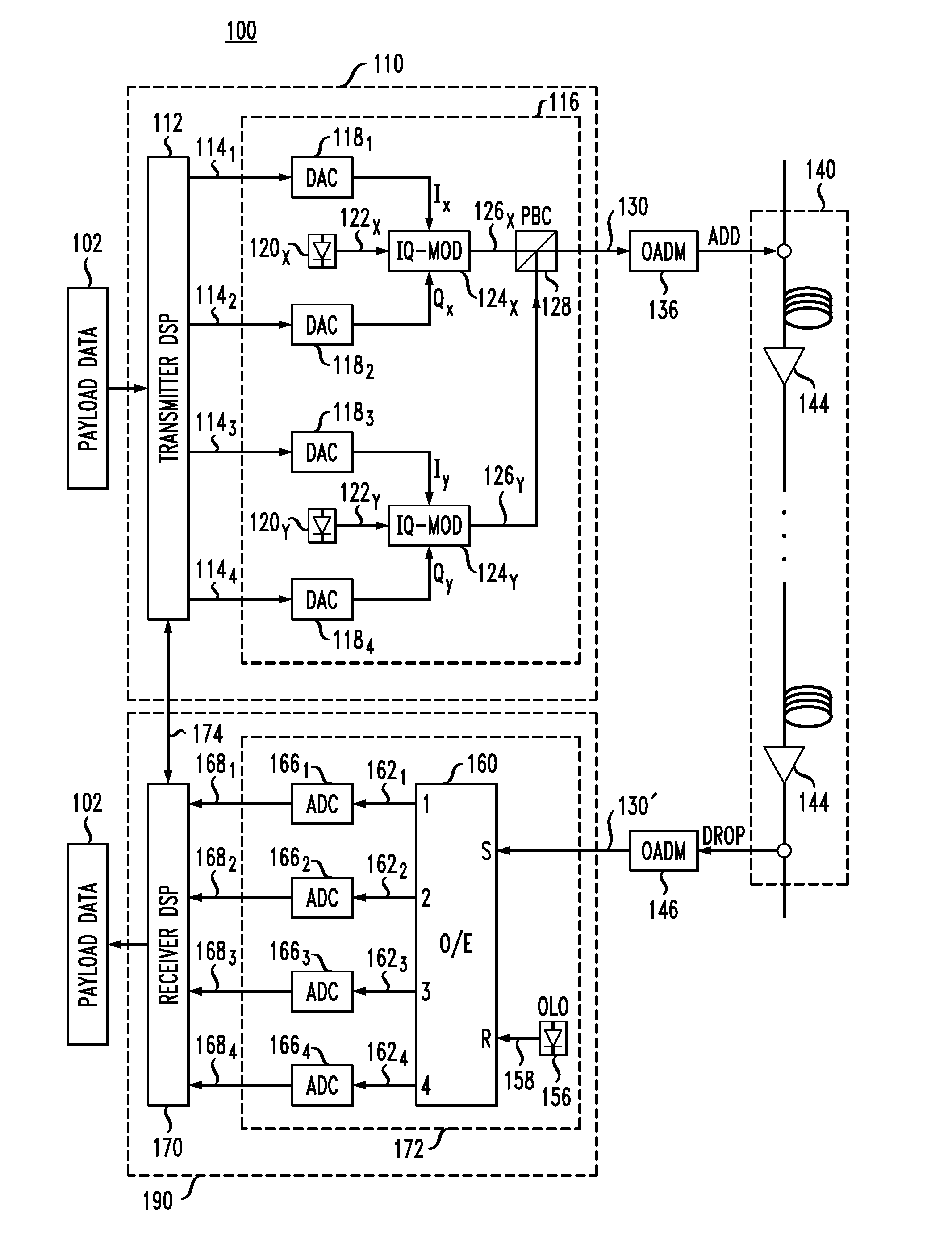
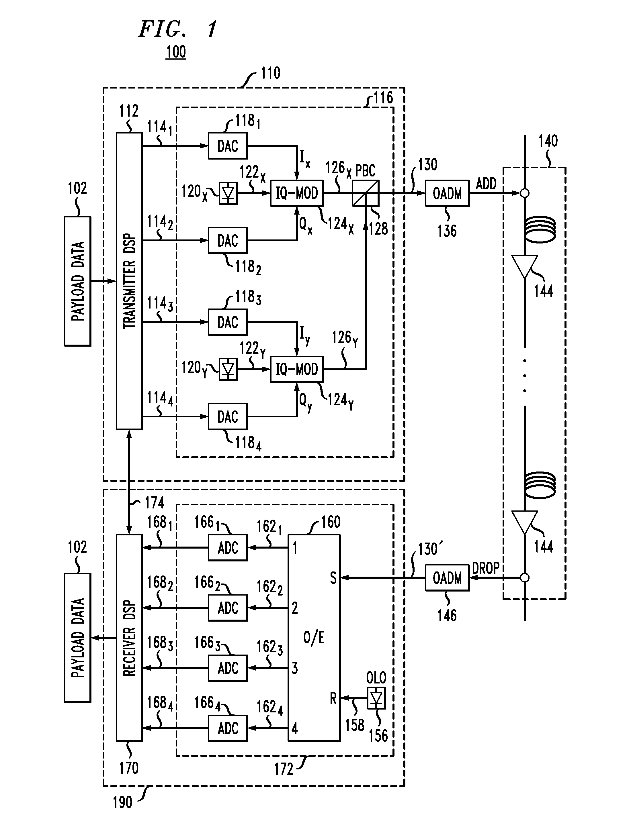
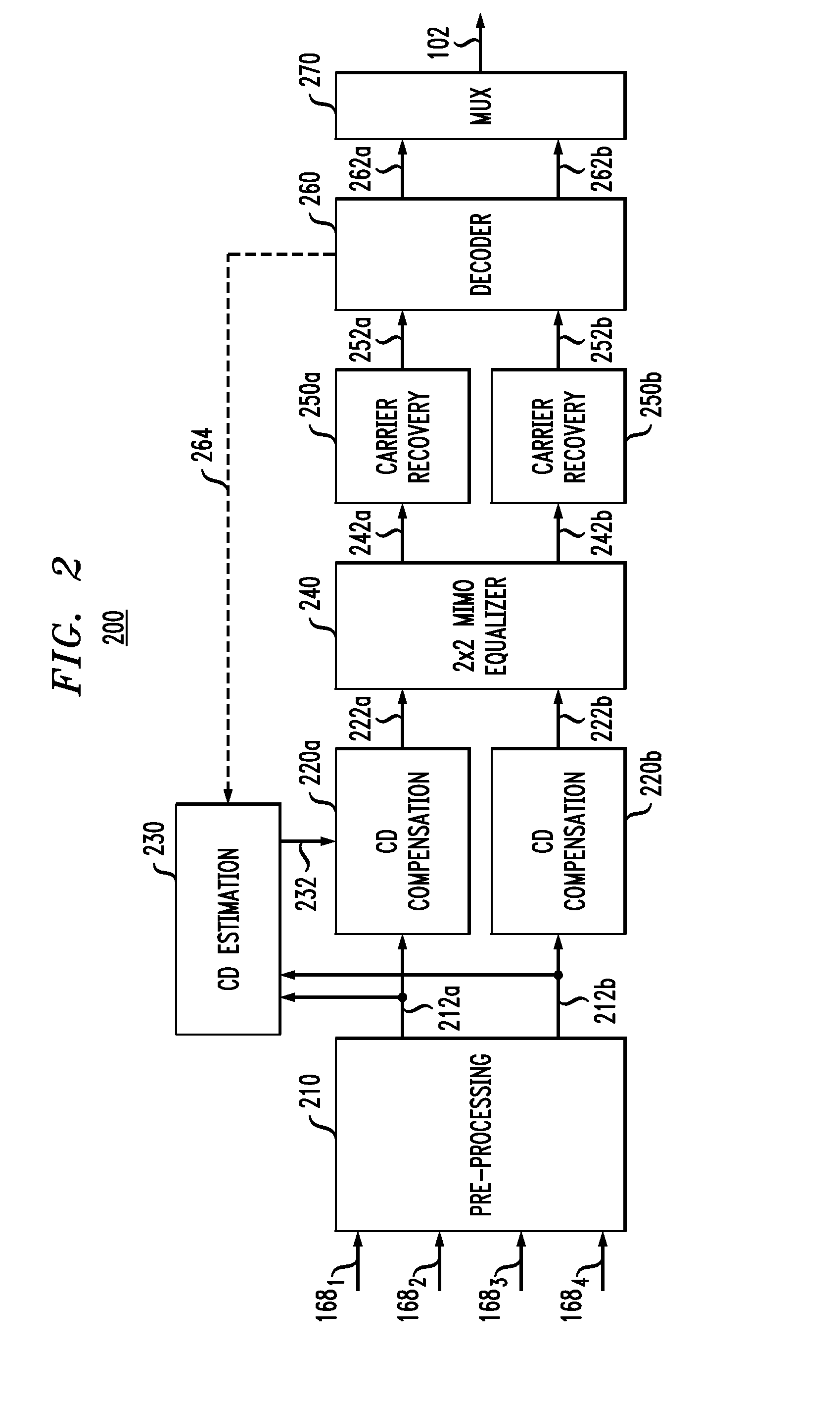
[0007]Disclosed herein are various embodiments of an optical receiver having an electronic dispersion-compensation module with two parallel signal-processing branches configured to provide a greater range of dispersion compensation than that provided by a prior-art device of comparable implementation complexity. In an example embodiment, each of the signal-processing branches includes a respective bank of finite-impulse-response filters that are configured in accordance with a different respective approximation of the group delay that needs to be compensated. The two group-delay approximations used by the filter banks rely on different respective step functions, each having a respective plurality of quantized steps, with the transitions between adjacent steps in one step function being spectrally aligned with the flat portions of the corresponding steps in the other step function. The filter banks may be further configured to apply different respective frequency-dependent phase-shif...


PUM


Abstract

An optical receiver having an electronic dispersion-compensation module with two parallel signal-processing branches configured to provide a greater range of dispersion compensation than that provided by a prior-art device of comparable implementation complexity. In an example embodiment, each of the signal-processing branches includes a respective bank of finite-impulse-response filters that are configured in accordance with a different respective approximation of the group delay that needs to be compensated. The two group-delay approximations used by the filter banks rely on different respective step functions, each having a respective plurality of quantized steps, with the transitions between adjacent steps in one step function being spectrally aligned with the flat portions of the corresponding steps in the other step function. The filter banks may be further configured to apply different respective frequency-dependent phase-shift and/or amplitude-scaling profiles designed to reduce signal distortions associated with the transitions between adjacent steps in the step functions.

Description

CROSS-REFERENCE TO RELATED APPLICATIONS[0001]This application claims priority from U.S. Provisional Patent Application No. 61 / 829,448, filed on May 31, 2013, and entitled “OPTICAL RECEIVER HAVING A CHROMATIC-DISPERSION COMPENSATION MODULE WITH A MULTIBRANCH FILTER-BANK STRUCTURE.”BACKGROUND[0002]1. Field[0003]The present disclosure relates to optical communication equipment and, more specifically but not exclusively, to optical receivers configured to perform chromatic-dispersion (CD) compensation processing.[0004]2. Description of the Related Art[0005]This section introduces aspects that may help facilitate a better understanding of the claimed invention(s). Accordingly, the statements of this section are to be read in this light and are not to be understood as admissions about what is in the prior art or what is not in the prior art.[0006]Chromatic dispersion (CD) is one of the most-common impairments in fiber-optic transmission systems. In coherent transmission, CD can be compens...

Claims


Application Information

Patent Timeline
IPC IPC(8): H04B10/61
CPCH04B10/6161H04B10/616
Inventor RANDEL, SEBASTIAN A.HAUSKE, FABIAN N.KANEDA, NORIAKI
Owner ALCATEL LUCENT SAS
Why Eureka
Try Eureka