Gantry Structure For A Hadron Therapy Apparatus

a technology of hadron and gantry, which is applied in the field of gantry structure for to a hadron therapy apparatus, can solve the problems of cumbersome frame, large space occupation, and huge investment in hospitals

Active Publication Date: 2014-12-04
ION BEAM APPL
View PDF3 Cites 10 Cited by
  • Summary
  • Abstract
  • Description
  • Claims
  • Application Information

AI Technical Summary

Benefits of technology

[0030]Near the beam inlet end, the beam delivery line is advantageously supported in an auxiliary inlet support, which is preferably adjustable and warrants that the beam inlet end of the pivotable beam delivery line is centered with regard to the terminal section of the fixed beam transport line to which it is connected. This auxiliary inlet support is advantageously a roller support located beneath the beam inlet end, where it cooperates with a cylindrical bearing surface arranged on the beam inlet end for centering the latter on the axis of rotation. It will be appreciated that the load to be supported by the auxiliary inlet support is only a very small fraction of the load supported by the pivotable support arm, so that this auxiliary inlet support is not very bulky.

Problems solved by technology

A common drawback of all known isocentric gantries is that they are cumbersome, require a lot of space and represent for hospitals a huge investment.
This cumbersome frame has to be rigid enough to support at least the weight of two heavy bending magnets and the heavy counterweight.
Such a gantry system is very cumbersome too.
However, it is obviously even a more cumbersome equipment than the prior art device discussed above.
There is consequently a first challenge for providing a more compact gantry structure for a hadron therapy apparatus than these prior art devices.
There is another challenge for providing such a compact gantry structure in which the support structure is subjected to more equal loads.
There is a still another challenge for providing such a compact gantry structure with a support structure that can be more easily integrated into a treatment room.
There is a further challenge for providing a such a gantry structure that can be easily transported, easily introduced into the treatment room and easily assembled in situ.
There is a further challenge for providing a gantry structure with a support structure warranting an easy access to the sub-equipments it supports.

Method used


Image

  • Gantry Structure For A Hadron Therapy Apparatus
  • Gantry Structure For A Hadron Therapy Apparatus
  • Gantry Structure For A Hadron Therapy Apparatus

Examples


Embodiment Construction

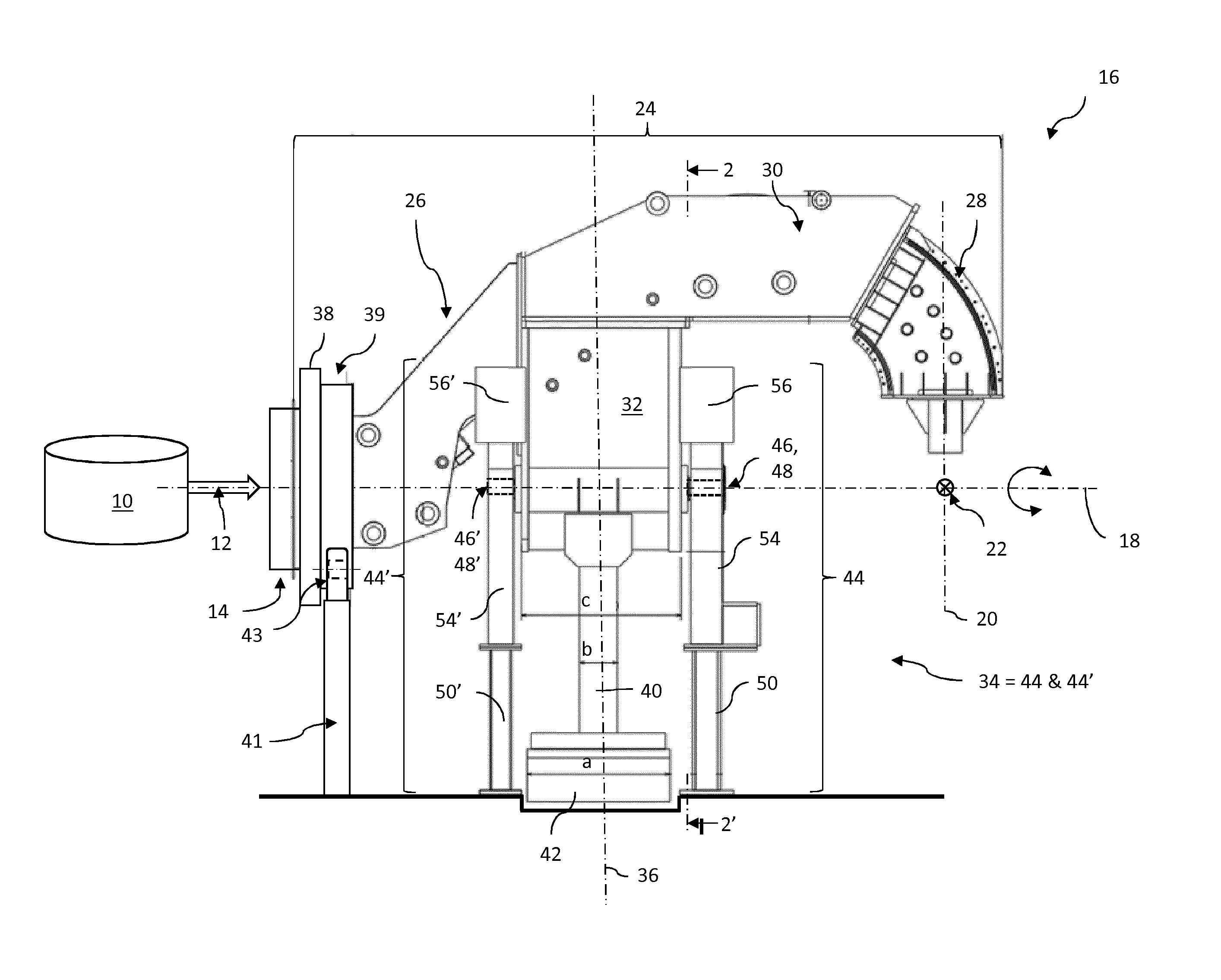
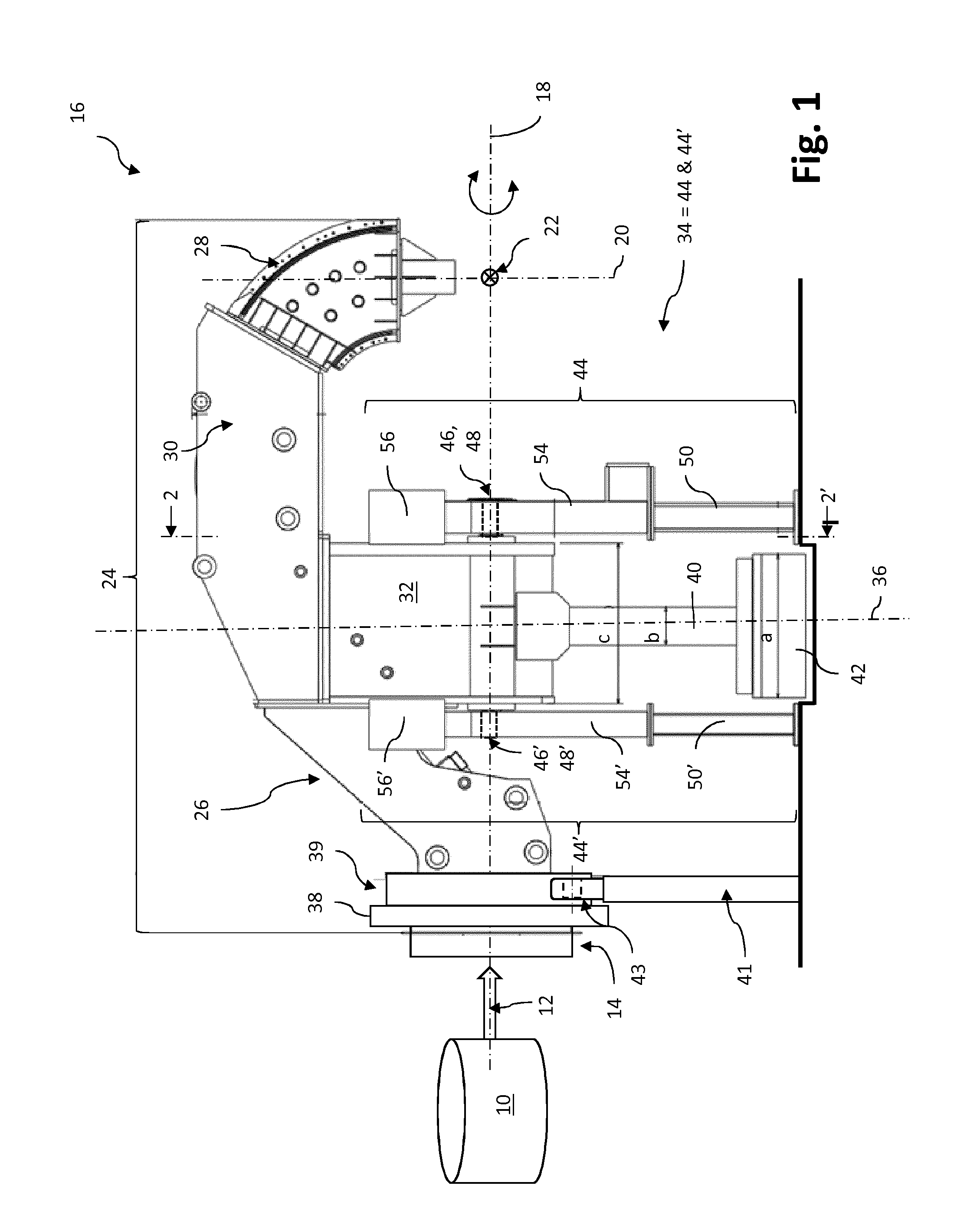
[0036]FIG. 1 shows a hadron therapy apparatus with a gantry structure in accordance with the present invention. Cylinder 10 schematically represent a hadron accelerator (not drawn to scale), which generates a beam of accelerated hadrons (schematically represented by arrow 12) guided through a beam transport line (represented by its terminal section 14).

[0037]Arrow 16 globally identifies a gantry structure of the hadron therapy apparatus. Whereas the beam transport line 14 is immobile, the gantry structure 16 connected to the beam transport line 14 is capable of pivoting about a horizontal axis of rotation 18. This pivotable gantry structure 16 is used to deliver the hadron beam from different angular positions onto a target volume, wherein the central axis of the beam is always contained in a plane 20 that is perpendicular to the axis of rotation 18 and intersects the axis of rotation 18 at a point 22, called isocenter 22. The target volume (e.g. a tumor to be irradiated) is centere...


PUM


Abstract

A gantry structure (16) designed for pivoting about an axis of rotation (18) and for delivering a hadron beam on a target comprises a beam delivery line (24) receiving the hadron beam in a direction essentially parallel to the axis of rotation (18), deviating it away from said axis of rotation (18) and delivering it so that the axis of the beam intersects the axis of rotation (18). The beam delivery line (24) is a self-supporting structure supported by a pivotable support arm (32) in proximity of the center of gravity of the beam delivery line (24). A counterweight (42) is supported by a support arm extension (40) on the other side of the axis of rotation (18) for compensating the moment of force due to the weight of the beam delivery line (24) and the support arm (32).

Description

TECHNICAL FIELD[0001]The present invention relates to a gantry structure for a hadron therapy apparatus and to a hadron therapy apparatus with a compact gantry structure.DESCRIPTION OF RELATED ART[0002]Radiotherapy using charged particles (e.g. protons, carbon ions, . . . ) has proven to be a precise and conformal radiation therapy technique, which allows to deliver a high dose to a target volume, while minimizing the dose to surrounding healthy tissues. In general, a particle therapy facility comprises an accelerator producing energetic charged particles, a beam transport system for guiding the particle beam to one or more treatment rooms and, for each treatment room, a particle beam delivery system. There are basically two types of beam delivery systems. Fixed beam delivery systems deliver the beam to the target volume from a fixed irradiation direction. Rotating beam delivery systems are capable of delivering the beam to the target volume from multiple irradiation directions. Suc...

Claims


Application Information

Patent Timeline
Patent Type & Authority Applications(United States)
IPC IPC(8): A61N5/10
CPCA61N2005/1087A61N5/1081
Inventor AMELIA, JEAN-CLAUDE
Owner ION BEAM APPL
Why Eureka
Try Eureka