

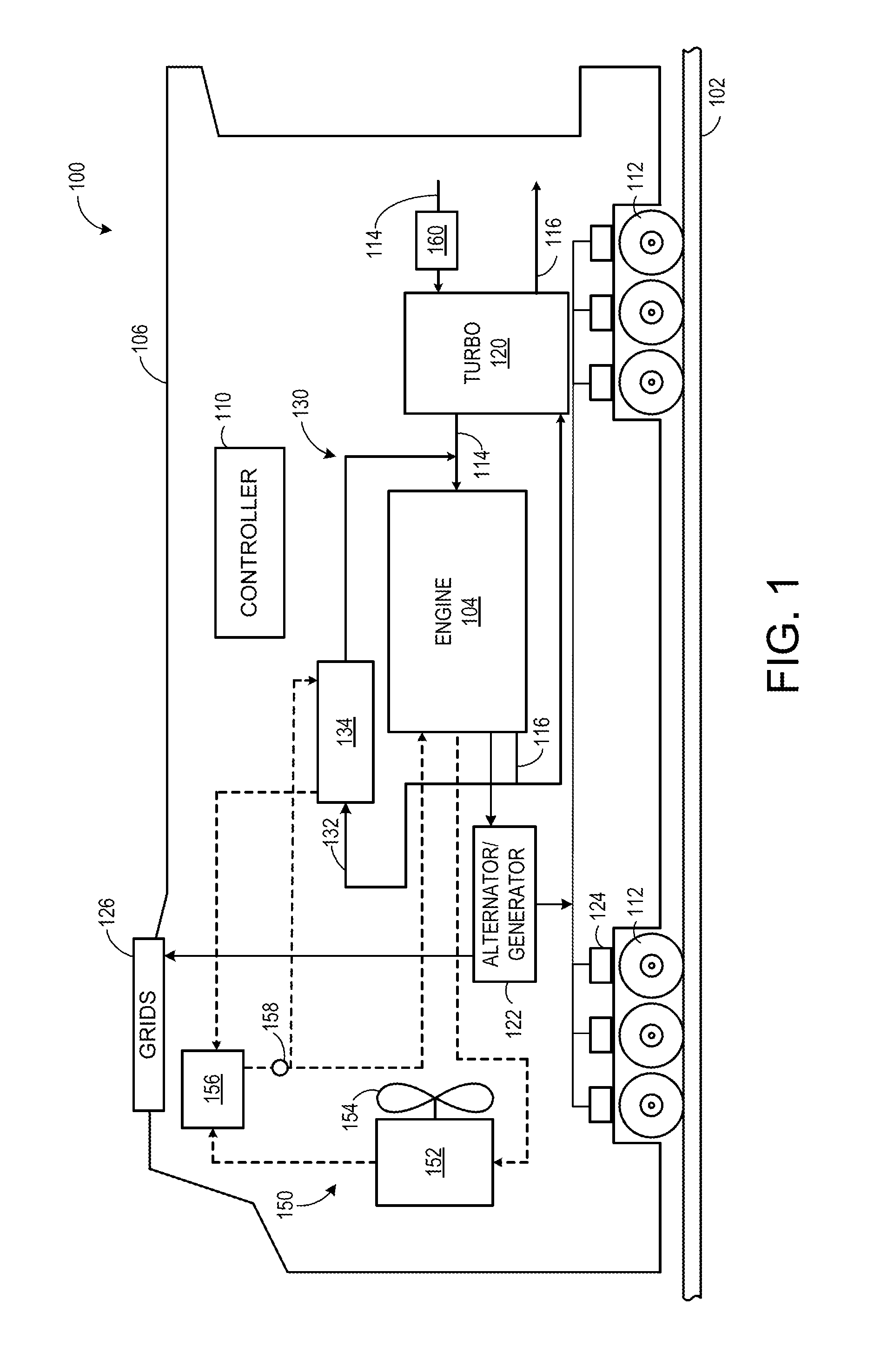
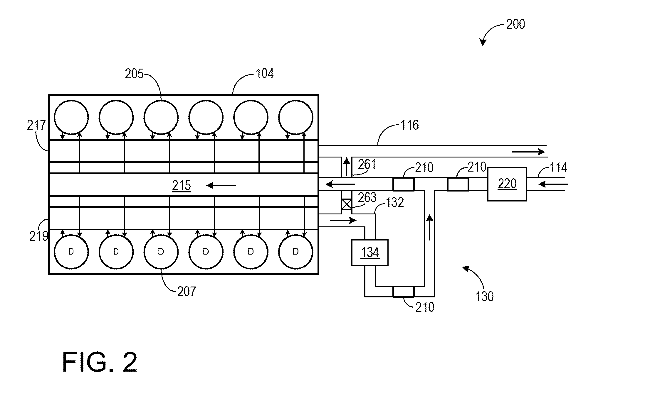
Method and systems for particle separation in an exhaust gas recirculation system
a particle separation and recirculation system technology, applied in the direction of separation process, auxillary pretreatment, filtration separation, etc., can solve the problems of internal generated wear debris or particles, further degradation of engine components, etc., and achieve the effect of reducing particle recirculation and engine degradation due to recirculated particles
- Summary
- Abstract
- Description
- Claims
- Application Information
AI Technical Summary
Benefits of technology
Problems solved by technology
Method used
Image

Examples
first embodiment
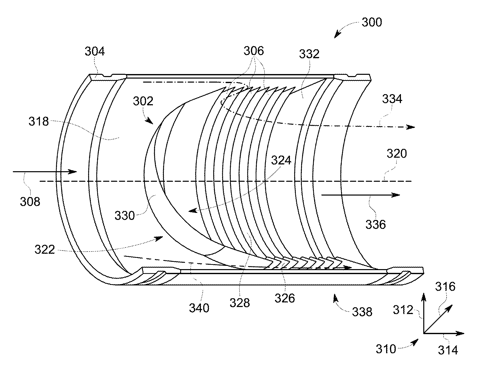
[0041]As discussed above, one type of particle separator positioned in a flow passage of an engine system may include an inertial-type particle separator. FIG. 3 shows an inertial-type particle separator 300. FIG. 3 includes a coordinate system 310 including a vertical axis 312, a horizontal axis 314, and a lateral axis 316. As shown in FIG. 3, the particle separator 300 includes a particle separating element 302 positioned within a gas flow passage 304. The gas flow passage 304 may be an EGR passage (such as EGR passage 132 shown in FIGS. 1-2) or an intake passage (such as intake passage 114 shown in FIGS. 1-2). Further, the gas flow passage 304 has a wall 318. The wall 318 is an interior wall forming a first diameter of the gas flow passage 304. Further, an interior of the gas flow passaged is defined by the wall 318.
[0042]The particle separating element 302 includes a plurality of overlapping and angled vanes 306 (also referred to as fins). Each vane of the plurality of vanes 306...
second embodiment
[0053]FIGS. 5-6 show an inertial-type particle separator 500. FIGS. 5-6 include a coordinate system 310 including a vertical axis 312, a horizontal axis 314, and a lateral axis 316. FIG. 5 is a side cross-sectional view of the particle separator 500. FIG. 6 shows a front (e.g., upstream) cross-sectional view of the particle separator 500.
[0054]As shown in FIGS. 5-6, the particle separator 500 includes a particle separating element 502 positioned within a gas flow passage 504. The gas flow passage 504 may be an EGR passage (such as EGR passage 132 shown in FIGS. 1-2) or an intake passage (such as intake passage 114 shown in FIGS. 1-2). Further, the gas flow passage 504 has a wall 518. The wall 518 is an interior wall forming a first diameter of the gas flow passage 504. Further, the wall 518 defines an interior of the gas flow passage 504.
[0055]The particle separating element 502 includes a plurality of overlapping and angled vanes 506. Specifically, the vanes 506 are linear slats wh...
PUM
| Property | Measurement | Unit |
|---|---|---|
| angle | aaaaa | aaaaa |
| diameter | aaaaa | aaaaa |
| diameter | aaaaa | aaaaa |
Abstract
Description
Claims
Application Information