Lightweight yoke for railway coupling

a coupler and light weight technology, applied in the field of railcars, can solve the problems of train delays, labor-intensive failure of couplers, etc., and achieve the effects of reducing thickness, reducing weight, and reducing strength to weight ratio

Active Publication Date: 2014-12-11
PENNSY CORP
View PDF4 Cites 3 Cited by
  • Summary
  • Abstract
  • Description
  • Claims
  • Application Information

AI Technical Summary

Benefits of technology

[0023]According to preferred embodiments, the yoke may be reduced in thickness in a given zone or area, such as a wall and the strength to weight ratio may remain the same as or greater than prior yokes having thicker walls, and even being heavier in weight. According to some preferred embodiments, the maximum wall thickness of the yoke may be about 1.15 inches, and, according to some embodiments, the yoke may have walls with thicknesses about 0.75″ or less. According to some preferred embodiments, the yoke wall thickness may be in a range from about 0.25 inches to about 1.25 inches. The present yoke, when used in a coupling assembly, also may improve payload to weight ratios, as a lightweight yoke may allow for more weight to be cargo or other payload, especially where a locomotive is pulling a great number of cars that have lightweight yokes.
[0024]According to some preferred embodiments, the weight reduction may be made at the back, nose end sections or straps of the yoke, and may be accomplished with coring, such as, for example, exterior coring. Embodiments may be produced with reduced weight by providing exterior coring on the side and back sections of the keyslot walls, straps or rear or nose sections.

Problems solved by technology

Couplers have a particular life, and in instances may fail.
The repair of a failed coupler can be labor intensive, can sometimes take place in very inclement weather and can cause train delays.

Method used


Image

  • Lightweight yoke for railway coupling
  • Lightweight yoke for railway coupling
  • Lightweight yoke for railway coupling

Examples


Embodiment Construction

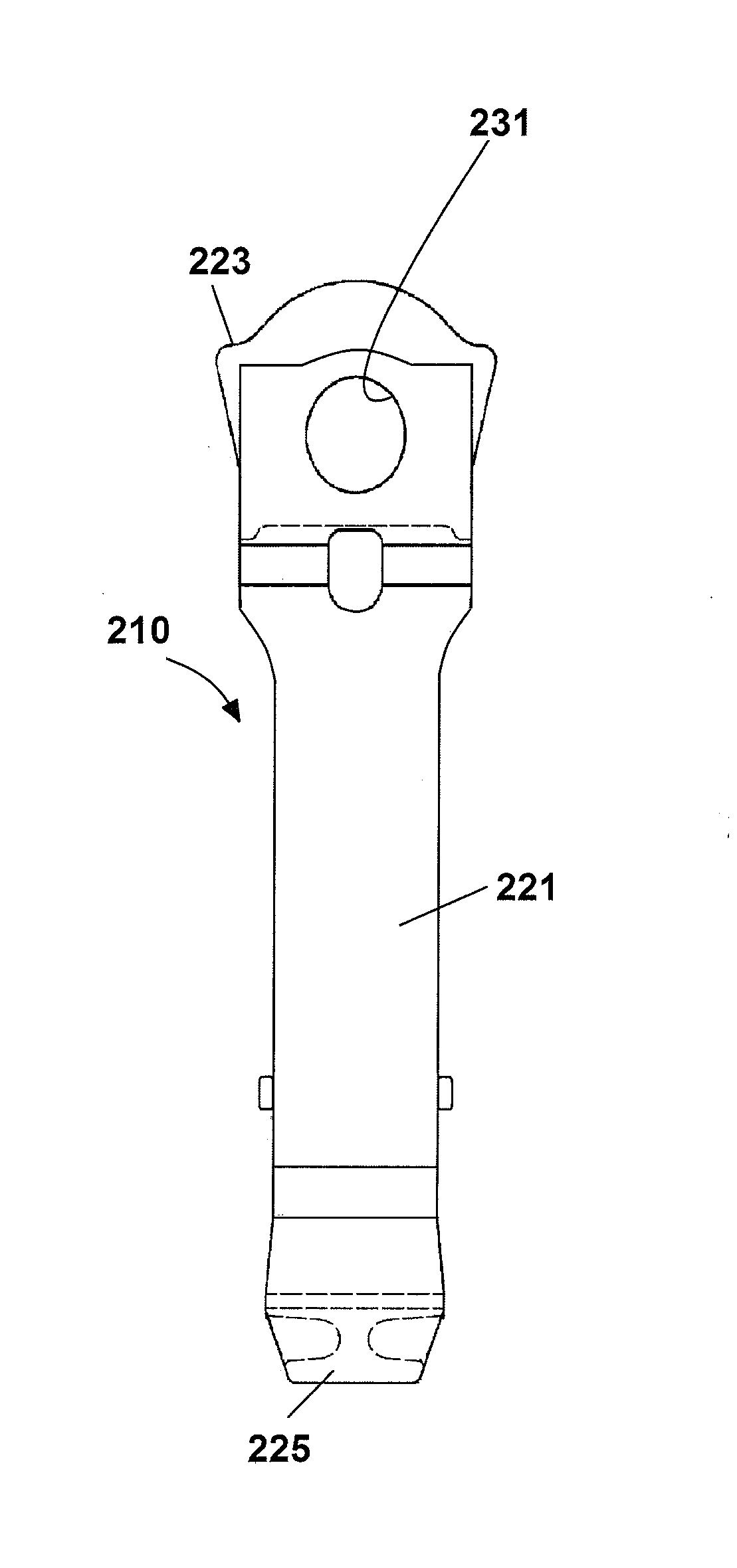
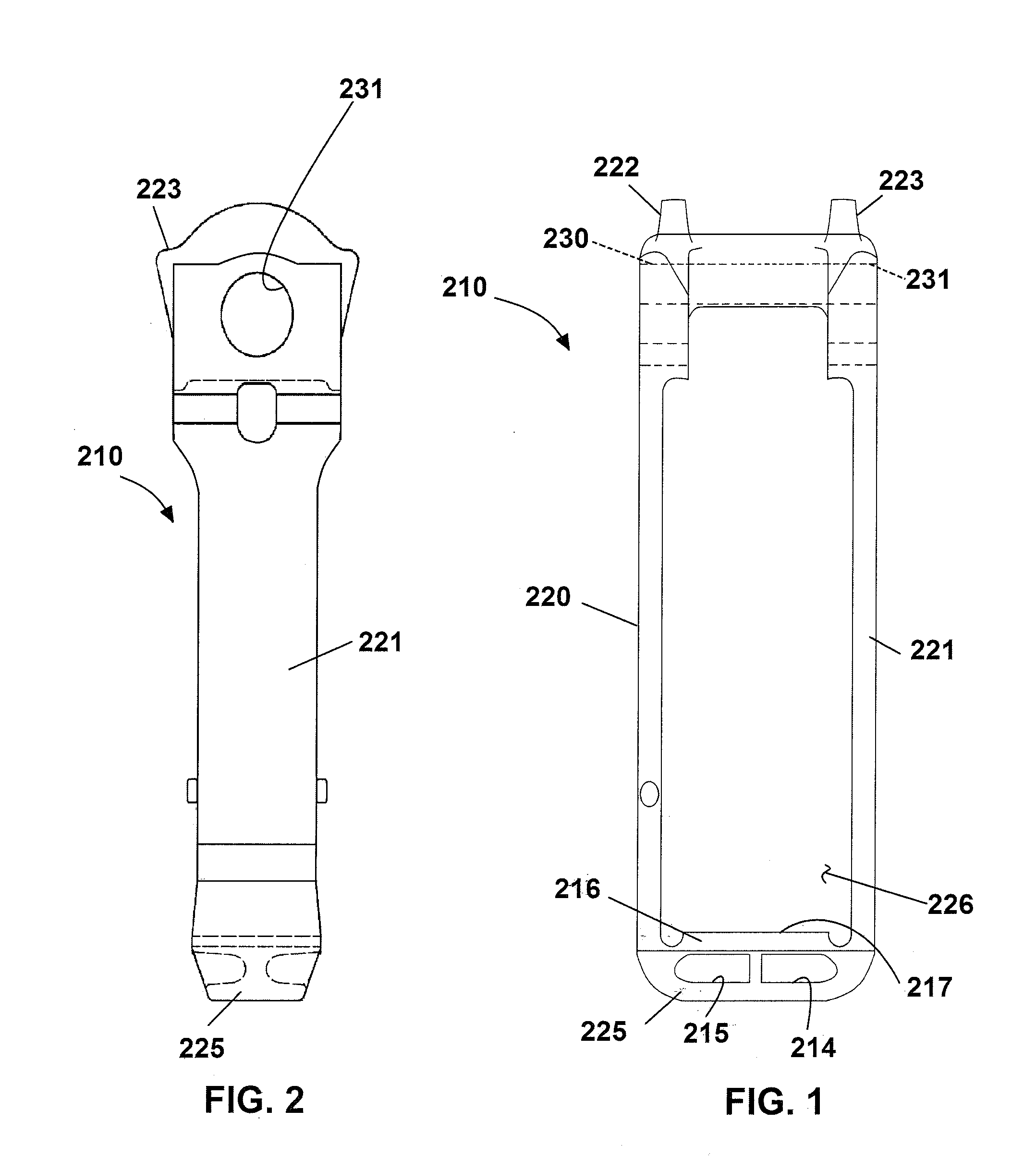
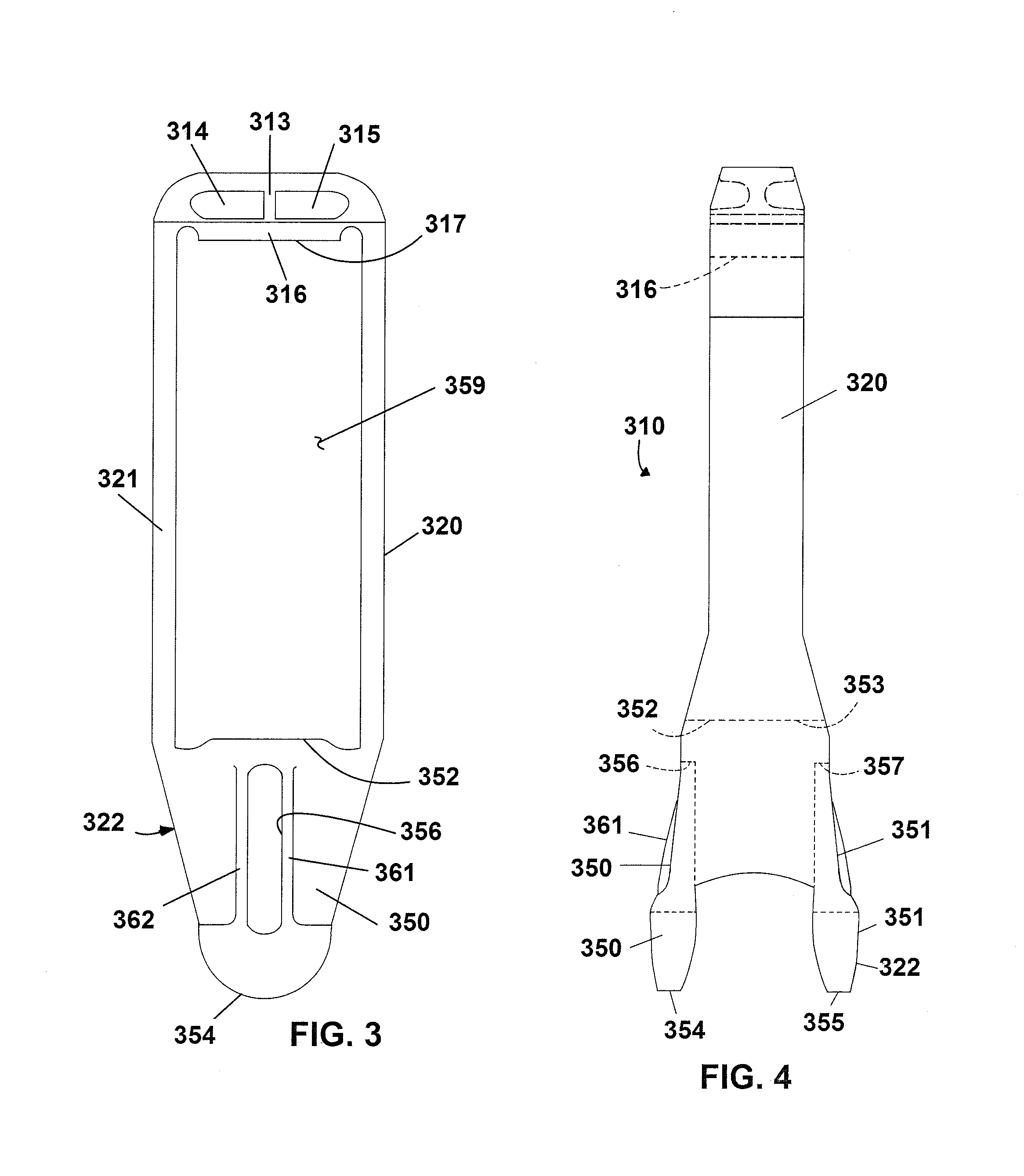
[0048]The present invention provides improved yokes which have improved strength and fatigue life. One way in which embodiments of the invention accomplish this is by providing coring (i.e., cavities) that may include interior coring, external coring, or both. The coring referred to may be cavities formed by traditional methods (where cores are used and placed in a mold) or cavities formed using other methods for producing the yoke or coupler). Another way in which embodiments of the invention accomplish this is by constructing the yoke from a material that is stronger than the grade E cast steel currently used. A further way in which embodiments of the invention accomplish this is by utilizing a material to construct the yoke that is stronger and lighter than the grade E cast steel currently used, while other embodiments provide a lightweight yoke by providing a unique geometry and using a material that is lighter than the current cast steel and / or stronger than the current cast st...


PUM

PropertyMeasurementUnit
thicknessesaaaaaaaaaa
thicknessaaaaaaaaaa

Abstract

Lightweight yokes are provided. According to some embodiments, the basic overall appearance of the yoke may be maintained, but the actual material of which it is constructed is changed. According to other embodiments, the yoke is provided with an improved lightweight construction, and, yet other embodiments the yoke may be provided with an improved construction and formed from a preferred material. Yokes may be constructed from cast austempered ductile iron; whereas cast iron has a density, 0.26 lbs/in̂3, which is approximately 8% less than steel, 0.283 lbs/in̂3, thereby allowing for a reduction in weight over steel. A suitable austempering process is used to produce the austempered metal yoke. Yokes have improved configurations which may require less metal to produce the yoke. Both, the lightweight material and improvements in configuration of the yoke structure may combine to provide a lighter weight yoke.

Description

BACKGROUND OF THE INVENTION[0001]1. Field of the Invention[0002]This invention relates in general to railcars and, more particularly, to railcar yokes for a coupler system.[0003]2. Brief Description of the Related Art[0004]Railcar couplers are disposed at each end of a railway car to enable joining one end of such railway car to an adjacently disposed end of another railway car. The engageable portion of each of these couplers is known in the railway art as a knuckle. For example, railway freight car coupler knuckles are taught in U.S. Pat. Nos. 4,024,958; 4,206,849; 4,605,133; and 5,582,307.[0005]Typically, adjacent railway cars are joined by heavy shafts extending from each car, known as couplers, and, generally, each coupler is engaged with a yoke housing a shock-absorbing element referred to as the draft gear. The type-E coupler is the standard coupler for railway freight cars. The type-E coupler has standard specifications such that producers making a type-E coupler adhere to a...

Claims


Application Information

Patent Timeline
Patent Type & Authority Applications(United States)
IPC IPC(8): B61G9/20B61G3/04
CPCB61G3/04B61G9/20
Inventor LEVITT, PERRYBROOK, ZACHARY RYANTAVARES, MANUELMURPHY, WAYNE H.STERN, AARONSCHMIDT, MICHAEL J.
Owner PENNSY CORP
Why Eureka
Try Eureka