

Electro-optic apparatus, method of manufacturing electro-optic apparatus, and electronic apparatus
a manufacturing method and electrooptic technology, applied in the direction of solid-state devices, semiconductor devices, thermoelectric devices, etc., can solve the problems of difficult to sufficiently secure a distance from the edge, loss of light-emitting functions of organic el elements, and improvement of sealing structures, etc., to achieve the effect of improving reliability and quality
- Summary
- Abstract
- Description
- Claims
- Application Information
AI Technical Summary
Benefits of technology
Problems solved by technology
Method used
Image

Examples
first embodiment
Electro-Optic Apparatus
[0046]First, as an example of an electro-optic apparatus according to this embodiment, an organic electroluminescence apparatus (hereinafter, referred to as an organic EL apparatus) is provided and described with reference to FIGS. 1 to 5.
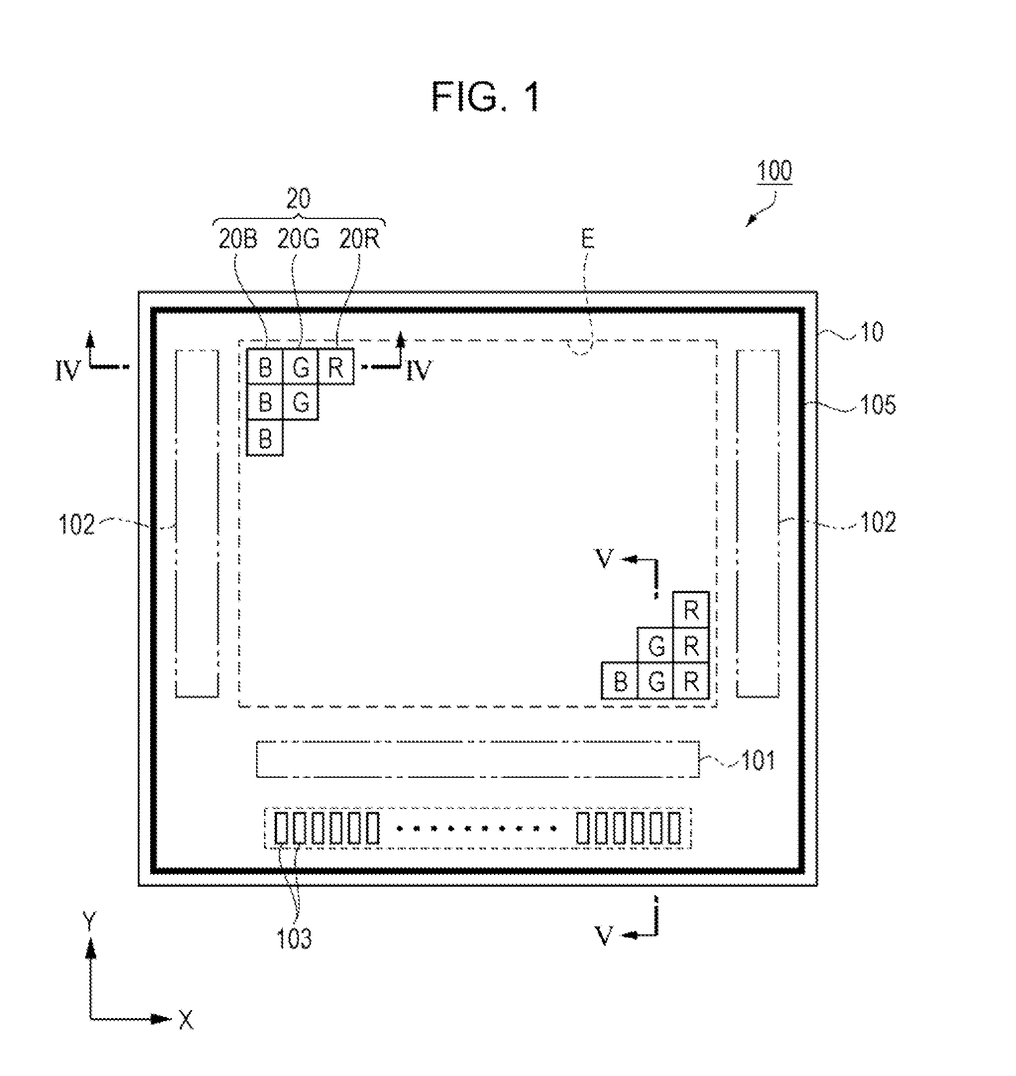
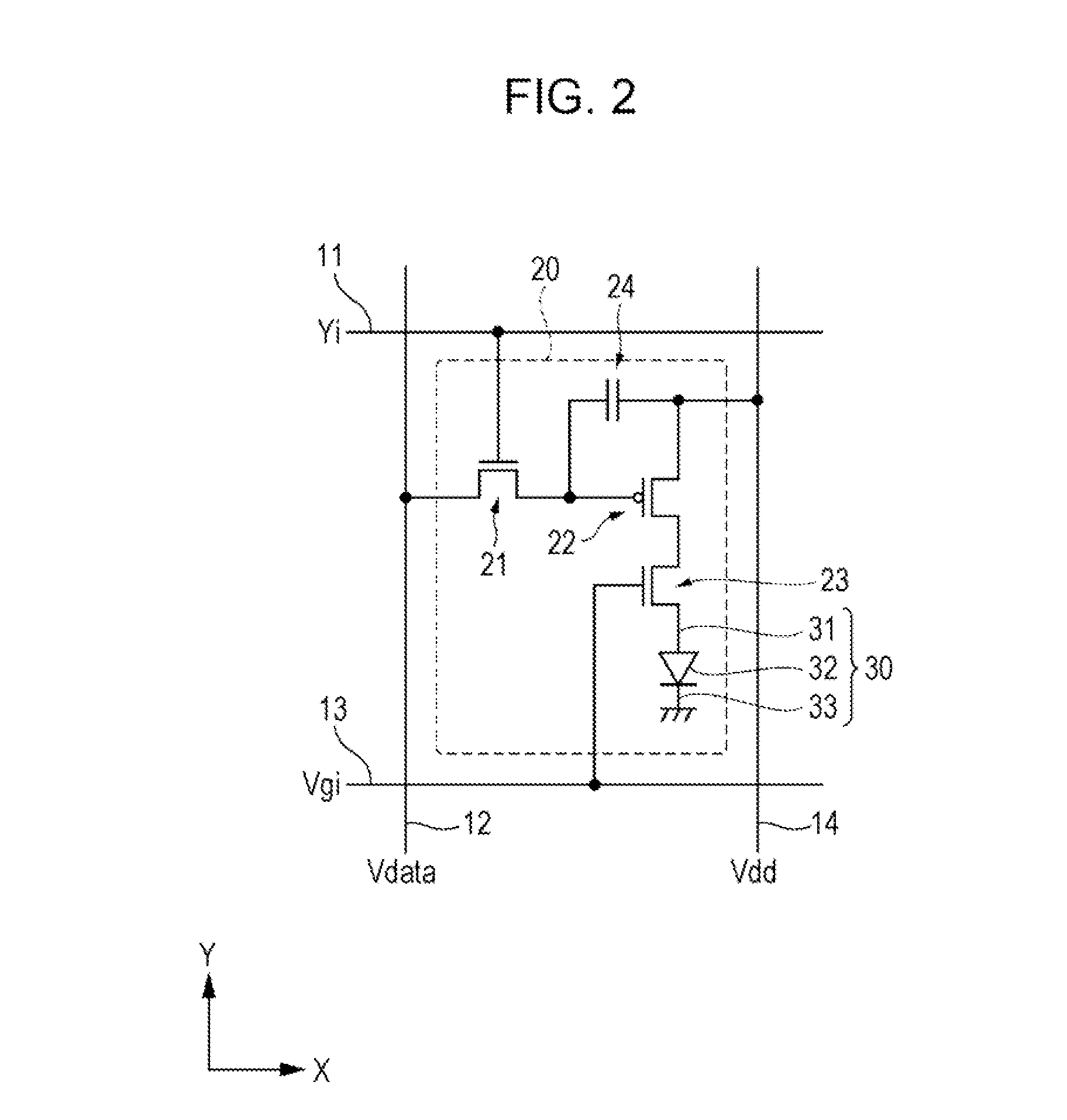
[0047]FIG. 1 is a schematic plan view illustrating the configuration of an organic EL apparatus as an electro-optic apparatus according to a first embodiment, FIG. 2 is an equivalent circuit diagram illustrating the electrical configuration of a light emitting pixel.
[0048]As shown in FIG. 1, an organic EL apparatus 100 as the electro-optic apparatus according to the embodiment includes an element substrate 10 as a substrate, a plurality of light emitting pixels 20 that are arranged in a matrix shape in a display area E as a first area of the element substrate 10, a data line drive circuit 101 and scan line drive circuits 102 that are peripheral circuits which controls the drive of the plurality of light emitting pixels 20, an...
second embodiment
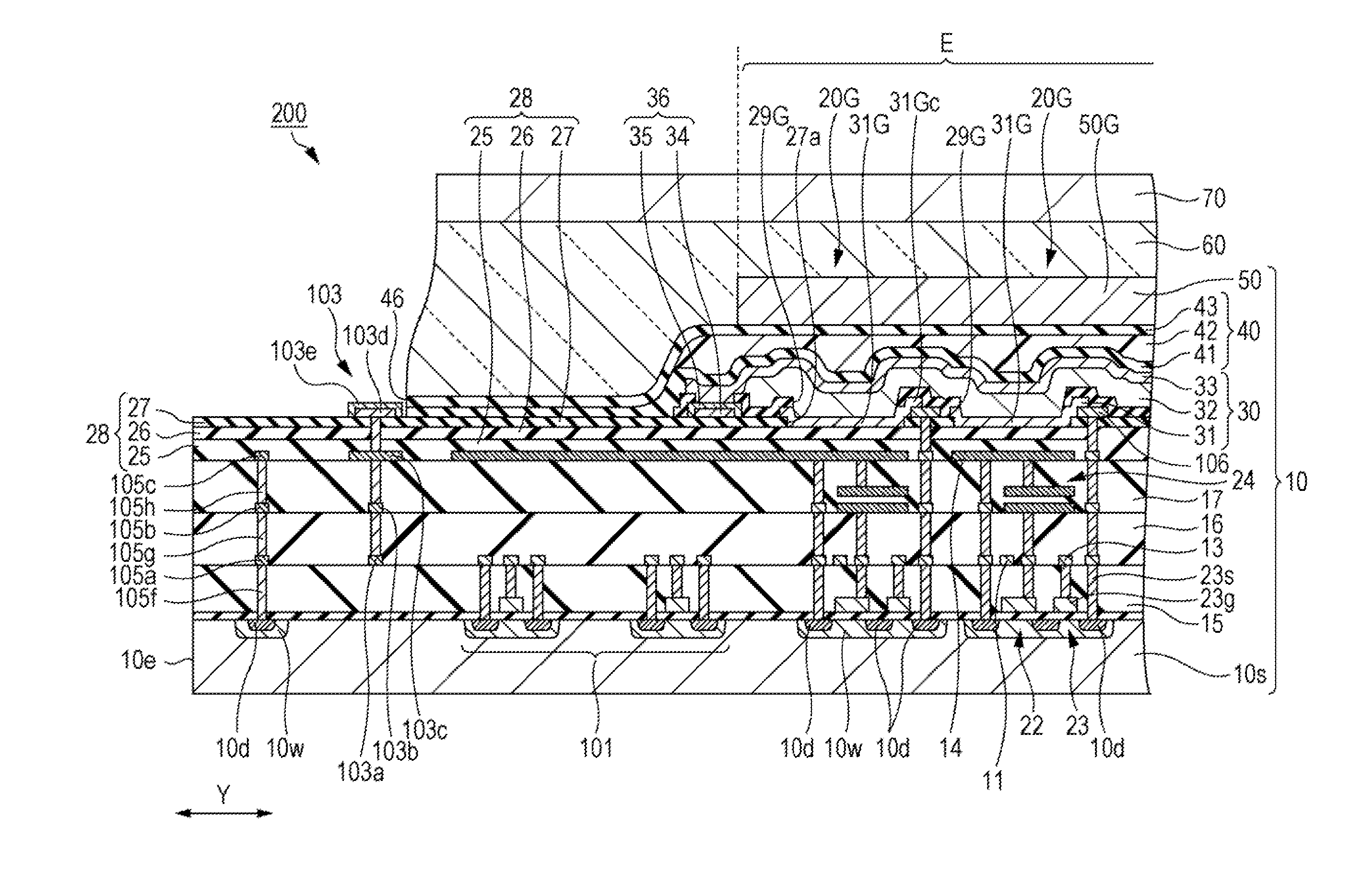
[0131]Subsequently, an electro-optic apparatus according to a second embodiment will be described with reference to FIGS. 7 and 8. FIG. 7 is a schematic plan view illustrating the configuration of an organic EL apparatus as the electro-optic apparatus according to the second embodiment, and FIG. 8 is a schematic cross-sectional view taken along a line VIII-VIII in FIG. 7.
[0132]The organic EL apparatus according to the second embodiment has a different range in which the sealing layer 40 is formed, compared to the organic ML apparatus 100 according to the first embodiment. Therefore, the same reference numerals denote the same configurations as in the first embodiment, and the detailed description thereof will not be repeated.
[0133]As shown in FIG. 7, an organic EL apparatus 200 according to the embodiment includes an element substrate 10, a plurality of light emitting pixels 20 (20B, 20G, and 20R) which are provided in a display area E on the element substrate 10, and a data line dr...
third embodiment
[0137]Subsequently, an electronic apparatus according to a third embodiment will be described with reference to FIG. 9. FIG. 9 is a schematic view illustrating a head-mounted display as an example of the electronic apparatus.
[0138]As shown in FIG. 9, a Head-Mounted Display (HMD) 1000 as the electronic apparatus according to the embodiment includes two display units 1001 which are provided to correspond to right and left eyes. When an observer M puts the head-mounted display 1000 on the head like glasses, it is possible to see letters, images, or the like which are displayed on the display units 1001. For example, if images are displayed on the right and left display units 1001 by taking a parallax into consideration, it is possible to see and enjoy three-dimensional images.
[0139]In the display units 1001, the organic EL apparatus 100 which is the spontaneous light emitting display apparatus according to the first embodiment (or the organic EL apparatus 200 according to the second em...
PUM
 Abstract
Description
Claims
Application Information