Lined sleeve for tube welding

Active Publication Date: 2014-12-11
NAT PINGTUNG UNIV OF SCI & TECH
View PDF20 Cites 3 Cited by
  • Summary
  • Abstract
  • Description
  • Claims
  • Application Information

AI Technical Summary

Benefits of technology

[0008]The primary objective of the present invention is to provide a lined sleeve for tube welding to effectively avoid stress concentration resul

Problems solved by technology

However, excessive fusion of the weld 9 occurs easily in the hollow tubes T1 and T2 such that a large diameter difference is generated between the weld 9 and the tubes T1 and T2.
In a case that the weldment is repeatedly subjected to stress, the diameter difference hinders smooth transmission of the stress and causes sharp corners between the weld 9 and the tubes T1 and T2, which results in stress concentration at t

Method used


Image

  • Lined sleeve for tube welding
  • Lined sleeve for tube welding
  • Lined sleeve for tube welding

Examples


Embodiment Construction

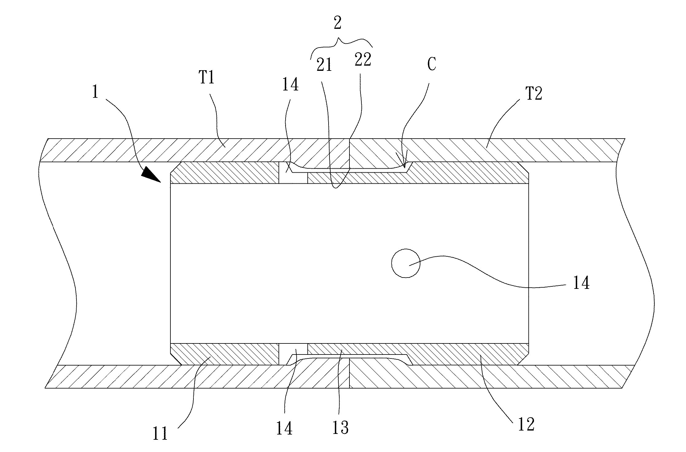
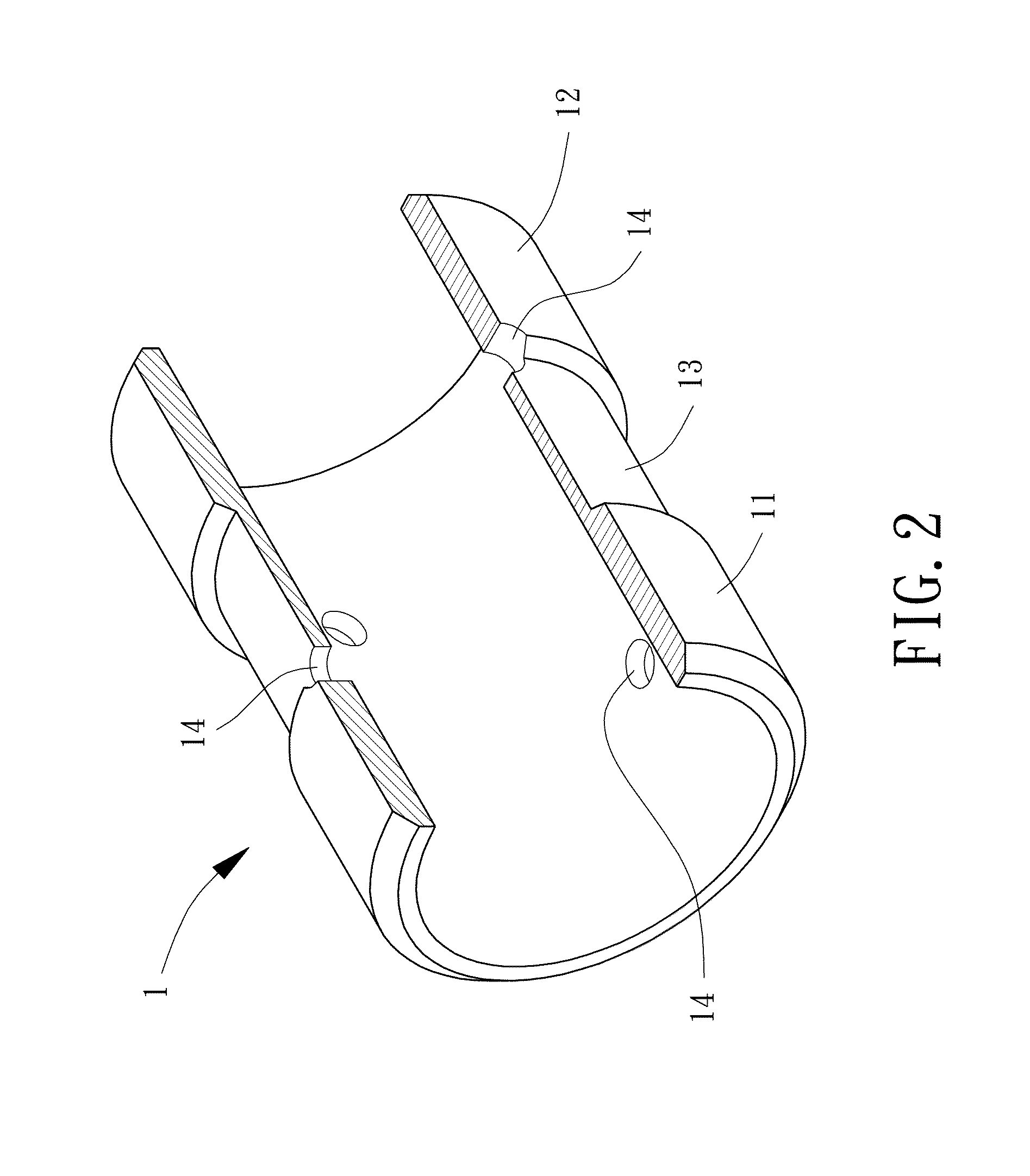
[0023]FIG. 2 shows a lined sleeve for tube welding of an example according to the present invention. The lined sleeve is in the form of an inner tube 1 including a first protruded portion 11 and a second protruded portion 12 respectively on opposite ends of the inner tube 1. The first protruded portion 11 and the second protruded portion 12 are adapted to be respectively received in two ends respectively of two tubes T1 and T2 to be welded together and are adapted to abut inner peripheries respectively of the tubes T1 and T2 (see FIGS. 3 and 4). The inner tube 1 further includes a recessed portion 13 between the first protruded portion 11 and the second protruded portion 12.

[0024]Preferably, the inner tube 1 further includes at least one through-hole 14 extending from an outer surface of the inner tube 1 through an inner surface of the inner tube 1. The at least one through-hole 14 can be located in the recessed portion 13, an intersection of the recessed portion 13 and the first pr...


PUM


Abstract

A lined sleeve for tube welding is in the form of an inner tube including a first protruded portion and a second protruded portion. The first protruded portion and the second protruded portion are respectively received in two ends respectively of two tubes to be welded together. The inner tube further includes a recessed portion between the first protruded portion and the second protruded portion.

Description

BACKGROUND OF THE INVENTION[0001]1. Field of the Invention[0002]The present invention relates to a lined sleeve for tube welding and, more particularly, to a lined sleeve mounted in two tubes to be welded together to avoid failure of the tubes resulting from excessive fusion in a root of a weld or resulting from a collapse in a surface of the weld.[0003]2. Description of the Related Art[0004]Arc, plasma, laser beam, and electron bean are generally used to join metals together through heating. Specifically, with reference to FIG. 1, two tubes T1 and T2 to be welded together are placed end to end to form a welding zone (the adjoining zone between the tubes T1 and T2). Local heating is carried out at the welding zone to increase the temperature of the welding zone to be higher than the melting point of the tube metals T1 and T2, causing local fusion of the tubes T1 and T2. A weld 9 is formed after cooling, and a weldment is obtained.[0005]However, excessive fusion of the weld 9 occurs ...

Claims


Application Information

Patent Timeline
IPC IPC(8): F16L13/02
CPCF16L13/0227B23K9/0282B23K9/0358B23K9/167B23K37/0531
Inventor TSENG, KUANG-HUNGHUANG, JIE-MENG
Owner NAT PINGTUNG UNIV OF SCI & TECH
Why Eureka
Try Eureka