Thermographic Inspection System for Composite Wind Turbine Blade

a composite wind turbine and inspection system technology, applied in the direction of material heat development, marine propulsion, vessel construction, etc., can solve the problems of significant damage, time-consuming and relatively expensive ultrasonic testing, and the difficulty of blade materials to penetrate through ultrasound

Active Publication Date: 2014-12-11
GENERAL ELECTRIC CO
View PDF3 Cites 6 Cited by
  • Summary
  • Abstract
  • Description
  • Claims
  • Application Information

AI Technical Summary

Problems solved by technology

Failure of the turbine blade along the bond joint could lead to significant damage.
Such ultrasonic testing, however, may be time consuming and relatively costly.
Moreover, some of the blade materials may be difficult to penetrate via ultrasound.
Specifically, certain areas of the blade may be obscured from ultrasonic testing because of the use of foam, balsa, or other types of core materials that may not pass typical ultrasonic frequencies therethrough.
Such microwave inspection, however, may be limited by exposure to radiation.

Method used


Image

  • Thermographic Inspection System for Composite Wind Turbine Blade
  • Thermographic Inspection System for Composite Wind Turbine Blade
  • Thermographic Inspection System for Composite Wind Turbine Blade

Examples


Embodiment Construction

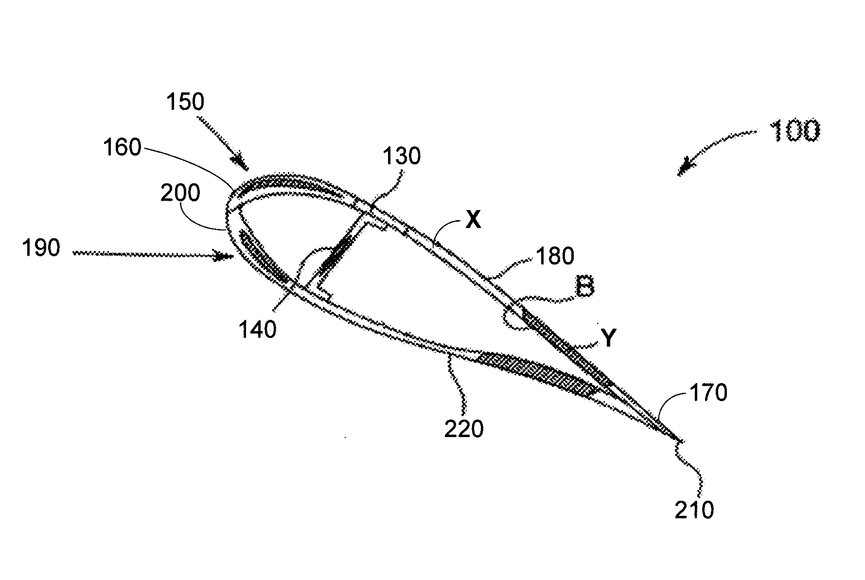
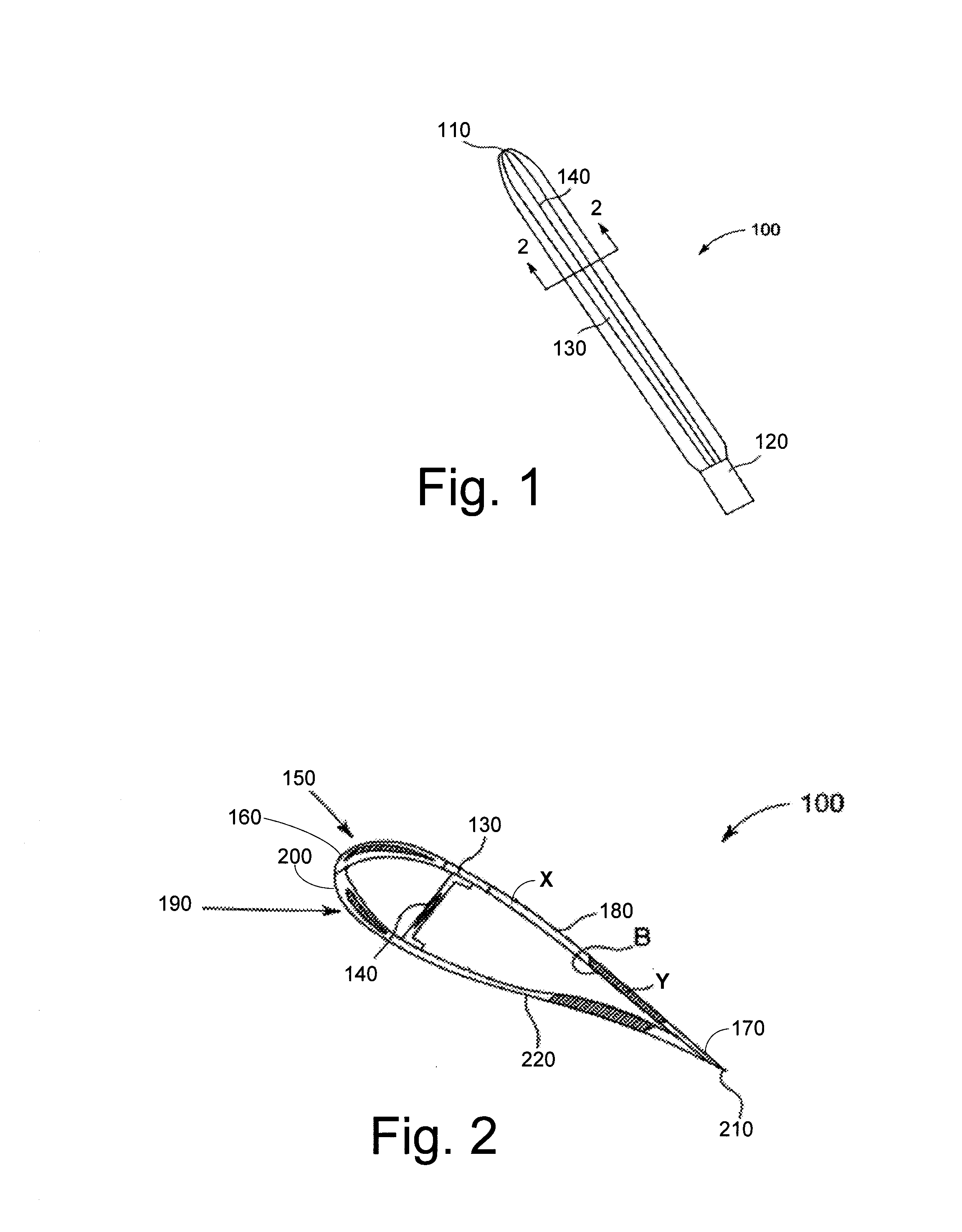
[0014]Referring now to the drawings, in which like numerals refer to like elements throughout the several views, FIGS. 1 and 2 show a wind turbine blade 100 as may be described herein. Generally described, the wind turbine blade 100 may be constructed of layers of an outer skin supported by a primary spar. Specifically, the wind turbine blade 100 may extend from a tip 110 to an opposing root 120. Extending between the tip 110 and the root 120 may be a spar cap 130 and a shear web 140. The shear web 140 may serve as the main structural support within the wind turbine blade 100. The spar cap 130 may be a glass portion running the length of the wind turbine blade 100 coincident with the shear web 140 so as to accommodate the tensile load on the wind turbine blade 100. The wind turbine blade 100 and the components thereof may have any size, shape, or configuration. Other components and other configurations also may be used herein.

[0015]As described above, the wind turbine blade 100 may ...


PUM

PropertyMeasurementUnit
widthaaaaaaaaaa
weightaaaaaaaaaa
rigidityaaaaaaaaaa

Abstract

The present application provides a method of inspecting a bond joint. The method may include the steps of applying an exothermic adhesive to a first shell and / or a second shell, attaching the first shell to the second shell via the exothermic adhesive to create the bond joint, allowing the exothermic adhesive to cure, and imaging the heat released by the exothermic adhesive along the bond joint. The bond joint may be a turbine blade bond joint.

Description

TECHNICAL FIELD[0001]The present application and resultant patent relate generally to wind turbine blades and inspection systems thereof and more particularly relate to a thermographic inspection system for a composite wind turbine blade bond joint using an exothermic adhesive.BACKGROUND OF THE INVENTION[0002]Modern wind turbine blades generally combine low weight and low rotational inertia with high rigidity and high resistance to fatigue and wear so as to withstand the various forces and the extreme conditions encountered over a typical life cycle. Generally described, the turbine blades may be formed from two shell halves. A critical step in the manufacture of the turbine blade is the closing of the two shell halves of the blade at a leading edge, a trailing edge, and at a spar cap union with a shear web via an adhesive to create a bond joint. Verifying the width and the overall integrity of this adhesive bond is required to ensure that the turbine blade will meet performance and...

Claims


Application Information

Patent Timeline
Patent Type & Authority Applications(United States)
IPC IPC(8): F01D5/12
CPCF01D5/12G01N25/48G01N25/72Y02E10/72Y10T29/49318
Inventor LAMBERTON, GARY AUSTINROSE, CURTIS WAYNE
Owner GENERAL ELECTRIC CO
Why Eureka
Try Eureka