Method and reference model for checking a measuring system

a technology of measuring system and reference model, which is applied in the direction of image data processing, dental prosthetics, sensors, etc., can solve the problems of user difficulty in determining whether the accuracy of calibration and/or registration is within the permissible tolerance limi

Active Publication Date: 2014-12-11
SIRONA DENTAL SYSTEMS
View PDF5 Cites 20 Cited by
  • Summary
  • Abstract
  • Description
  • Claims
  • Application Information

AI Technical Summary

Benefits of technology

[0047]This means that the dental measuring system may be checked under realistic measuring conditions.
[0048]The present method for checking measuring systems is particularly suitable for quality control when producing such measuring systems at the manufacturer's. The present method may also be used, however, for a recheck of such measuring systems at consumers, for example in a

Problems solved by technology

A disadvantage of this method is that the dimensions of the reference model, just as the distance between the last teeth of the maxilla or the mandible, must either be precisely measured or already known in order to enable a comparison.
Marking with false color

Method used


Image

  • Method and reference model for checking a measuring system
  • Method and reference model for checking a measuring system
  • Method and reference model for checking a measuring system

Examples


Embodiment Construction

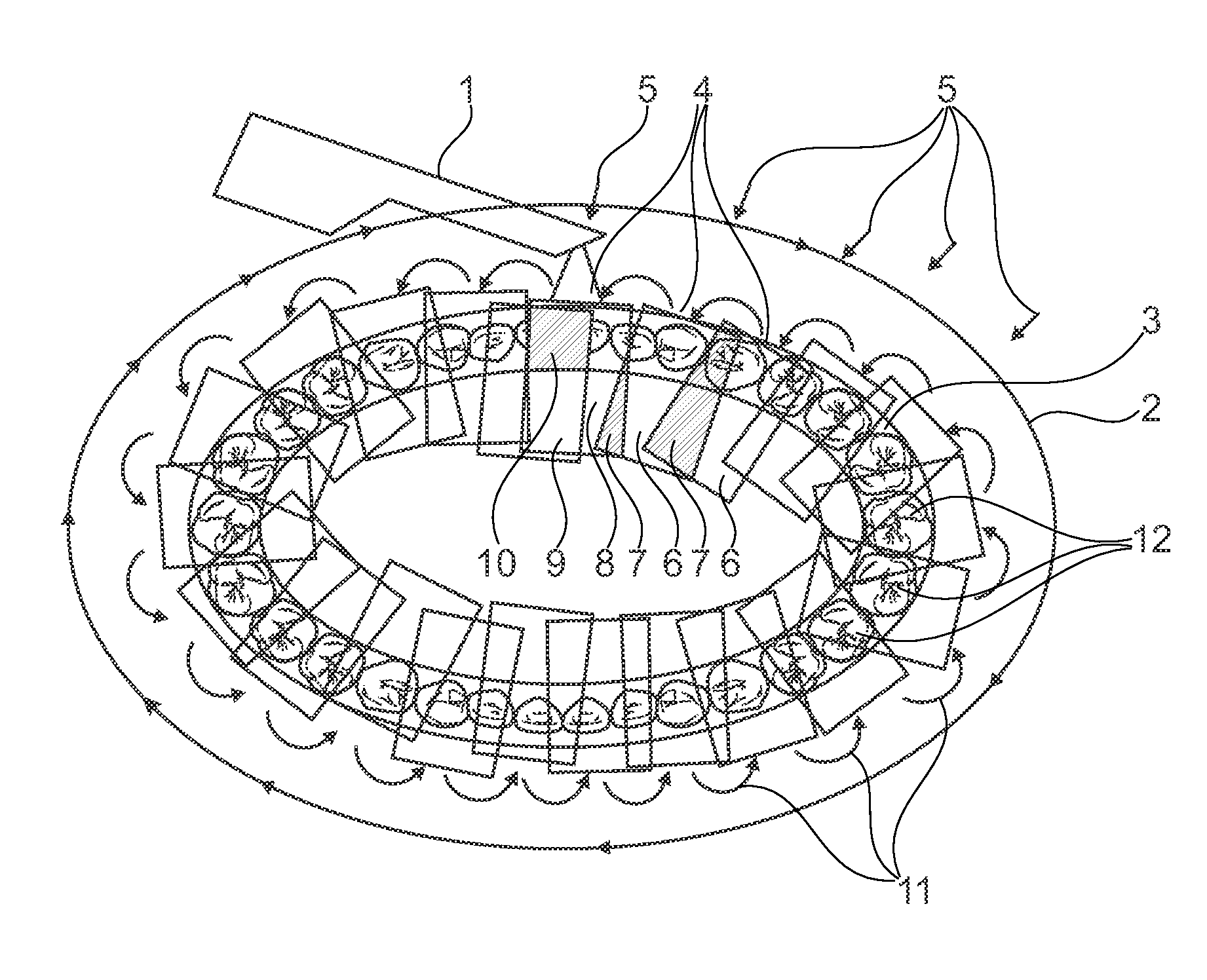
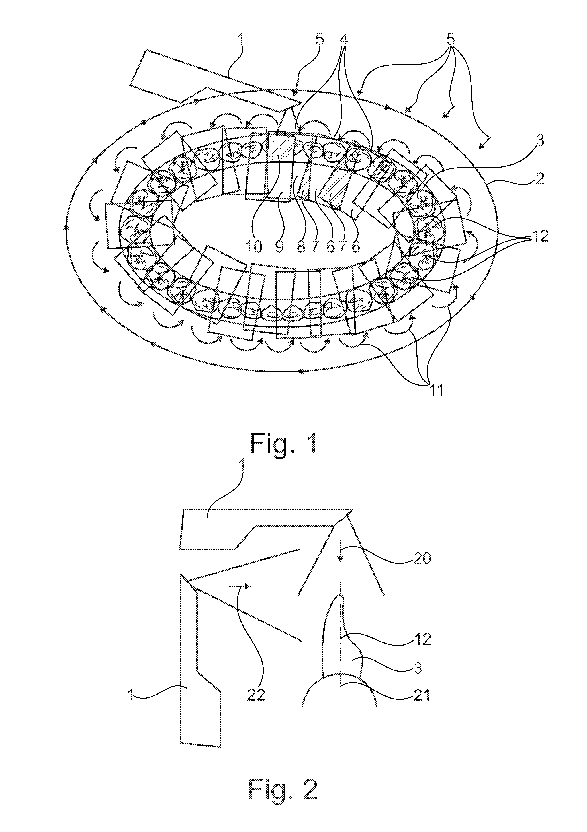
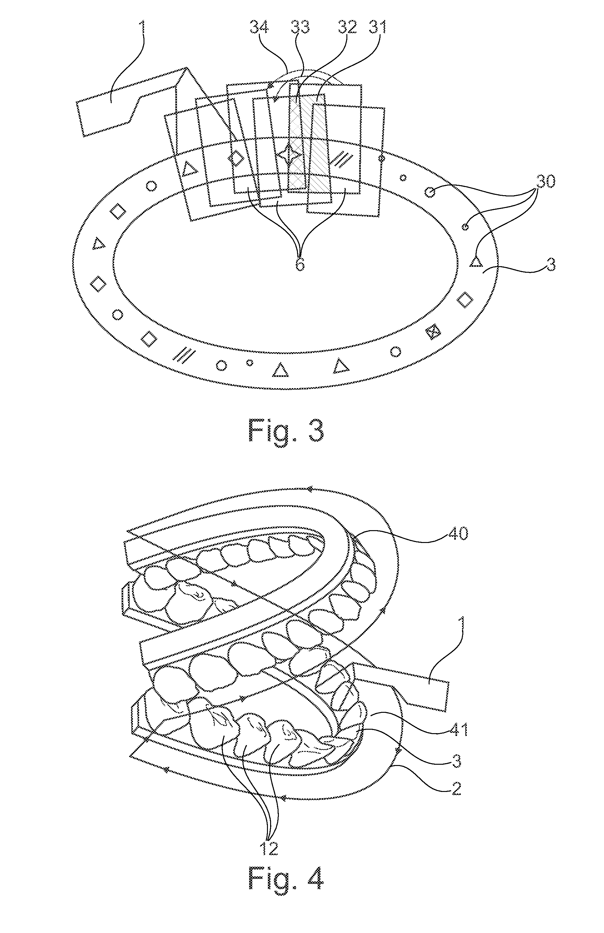
[0007]The invention relates to a method for checking a measuring system, wherein a plurality of three-dimensional images of a reference object are recorded from different image directions by means of the measuring system. The reference object in this case has a closed shape. Each of these three-dimensional images is registered at least with the preceding image, during which, with a faulty calibration and / or with a faulty registration, the individual images are deformed in comparison to the actual shape of the reference object, which means that the deformation continues when combining the individual three-dimensional images to form an overall image, and the overall image generated deviates in its dimensions from the dimensions of the reference object as a result thereof. In this process, at least one object region of the reference object is measured twice, at the beginning of a circuit and at the end of the circuit. A distance is then determined in the overall image between a first p...


PUM


Abstract

The invention relates to a reference object (3) and a method for checking a measuring system (1), wherein a plurality of three-dimensional recordings (4, 8) of a reference object are recorded from different recording directions (5) by means of the measuring system (1). The reference object (3) has a closed shape, wherein each of the three-dimensional recordings (4) is registered with at least the preceding recording (4). In the case of a faulty calibration and/or in the case of a faulty registration, the individual recordings (4, 8) are deformed compared to the actual shape of the reference object (3), so that the deformation continues when assembling the individual three-dimensional recordings (4) to form an overall recording (54) and the generated overall recording (54) deviates in its dimensions from the dimensions of the reference object (3) as a result thereof. At least one object region (10) of the reference object (3) is measured twice, at the beginning of a circuit and at the end of the circuit, wherein a distance (55) is determined in the overall recording (54) between a first position of the object region (10) in a first recording at the beginning of the circuit and a second position of the object region (10) in a second recording at the end of the circuit.

Description

TECHNICAL FIELD[0001]The invention relates to a method for checking a measuring system, wherein a plurality of three-dimensional images of a reference object are recorded from different image directions by means of the measuring system.PRIOR ART[0002]A plurality of methods for checking a measuring system are known from the prior art.[0003]In a first method, a reference model is measured by means of a precise laboratory system in a first step, and a 3-D model of the reference model is generated in doing so. Then, in a second step, the same reference model is measured by means of the measuring system to be checked, and a second 3-D model is generated. Subsequently, the first 3-D model measured with the laboratory system is compared with the second 3-D model. The difference between the two 3-D models then indicates a faulty calibration or registration. The difference between the 3-D models can be shown, for example, with false color markings. An average value of the deviation can also ...

Claims


Application Information

Patent Timeline
IPC IPC(8): A61B6/00G06T7/00G06T19/20
CPCA61B6/582G06T2219/2004G06T7/002G06T19/20A61B5/1077A61B5/1079G09B23/283A61B2560/0233G01B21/042A61C9/006A61C9/0066A61C13/34A61C19/04G06T2207/30036G06T2207/30204G06T7/80G06T7/85
Inventor POPILKA, BJORNWEDLER, VOLKERADAMSON, ANDERSTHIEL, FRANK
Owner SIRONA DENTAL SYSTEMS
Why Eureka
Try Eureka