
Cyclone dust collector and vacuum cleaner having the same

a vacuum cleaner and dust collector technology, applied in the field of vacuum cleaners, can solve the problems of not easy for users to determine whether or not the cyclone dust collector is working properly, suction force and cleaning efficiency are degraded, and users may fail to recognize the sam

Active Publication Date: 2014-12-18
SAMSUNG ELECTRONICS CO LTD
View PDF5 Cites 38 Cited by
  • Summary
  • Abstract
  • Description
  • Claims
  • Application Information

AI Technical Summary

Benefits of technology

The invention includes a part that prevents the indicator from getting separated from the outlet. This prevents liquid or gas from leaking out of the system.

Problems solved by technology

Accordingly, it is not easy for a user to determine whether or not the cyclone dust collector is operating normally.
That is, in the case that the fan motor malfunctions or a flow passage is blocked, suction force and cleaning efficiency are degraded, but the user may fail to recognize the same.

Method used


Image

  • Cyclone dust collector and vacuum cleaner having the same
  • Cyclone dust collector and vacuum cleaner having the same
  • Cyclone dust collector and vacuum cleaner having the same

Examples


Embodiment Construction

[0051]Reference will now be made in detail to the embodiments of the present invention, examples of which are illustrated in the accompanying drawings, wherein like reference numerals refer to like elements throughout.

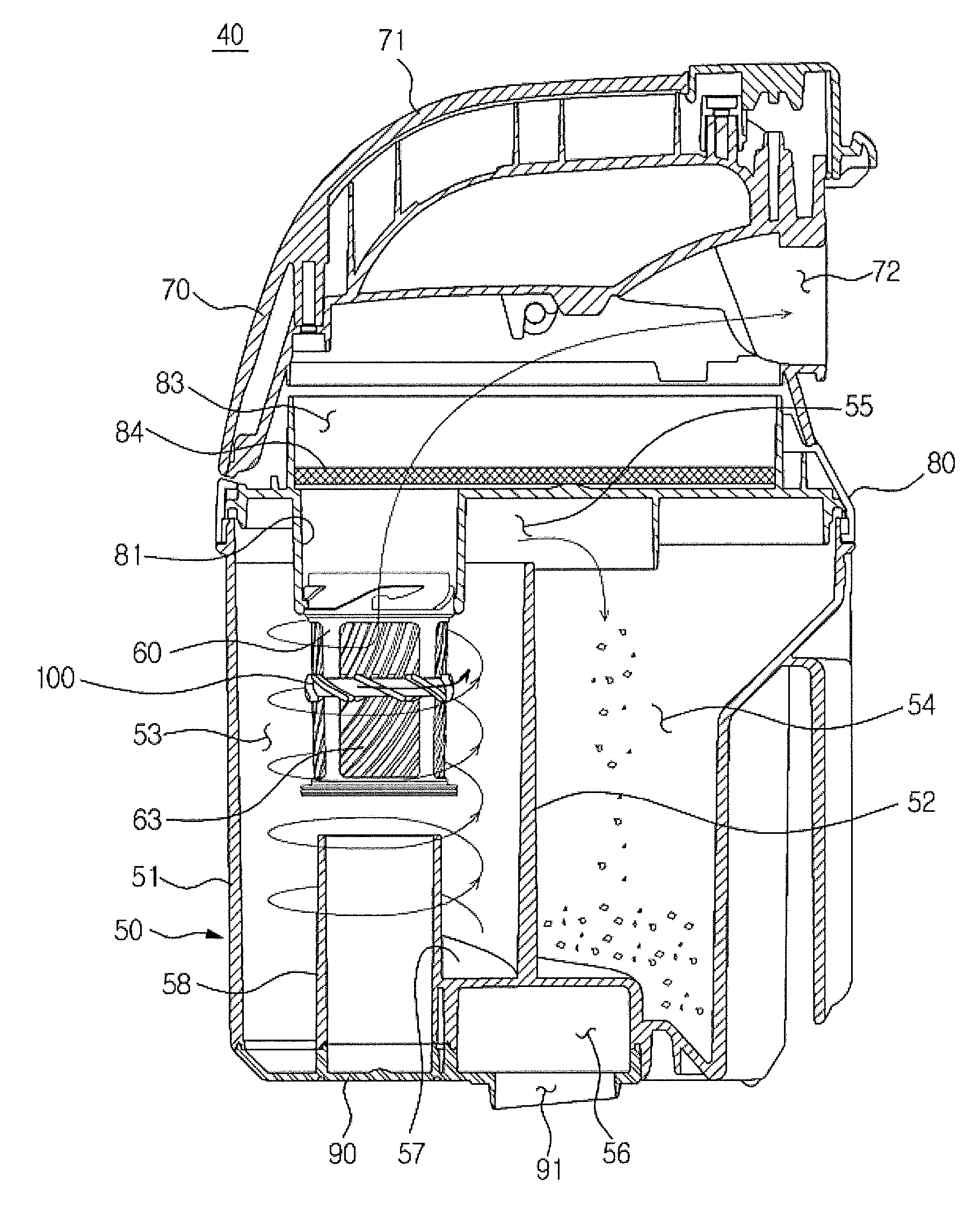
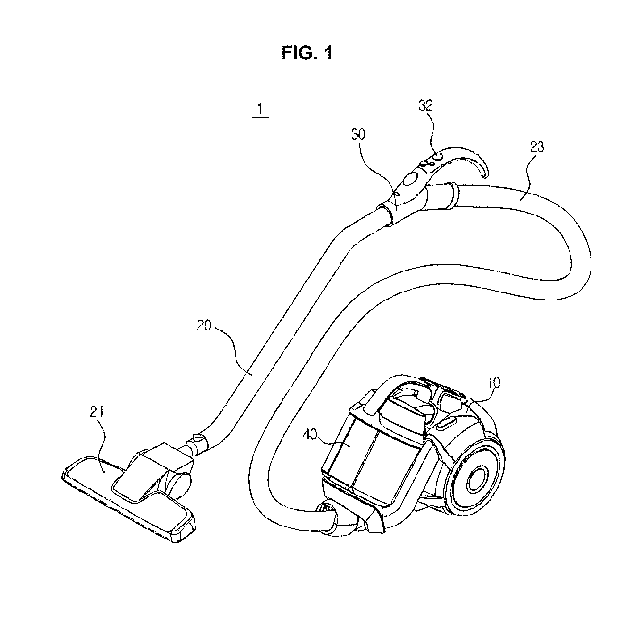
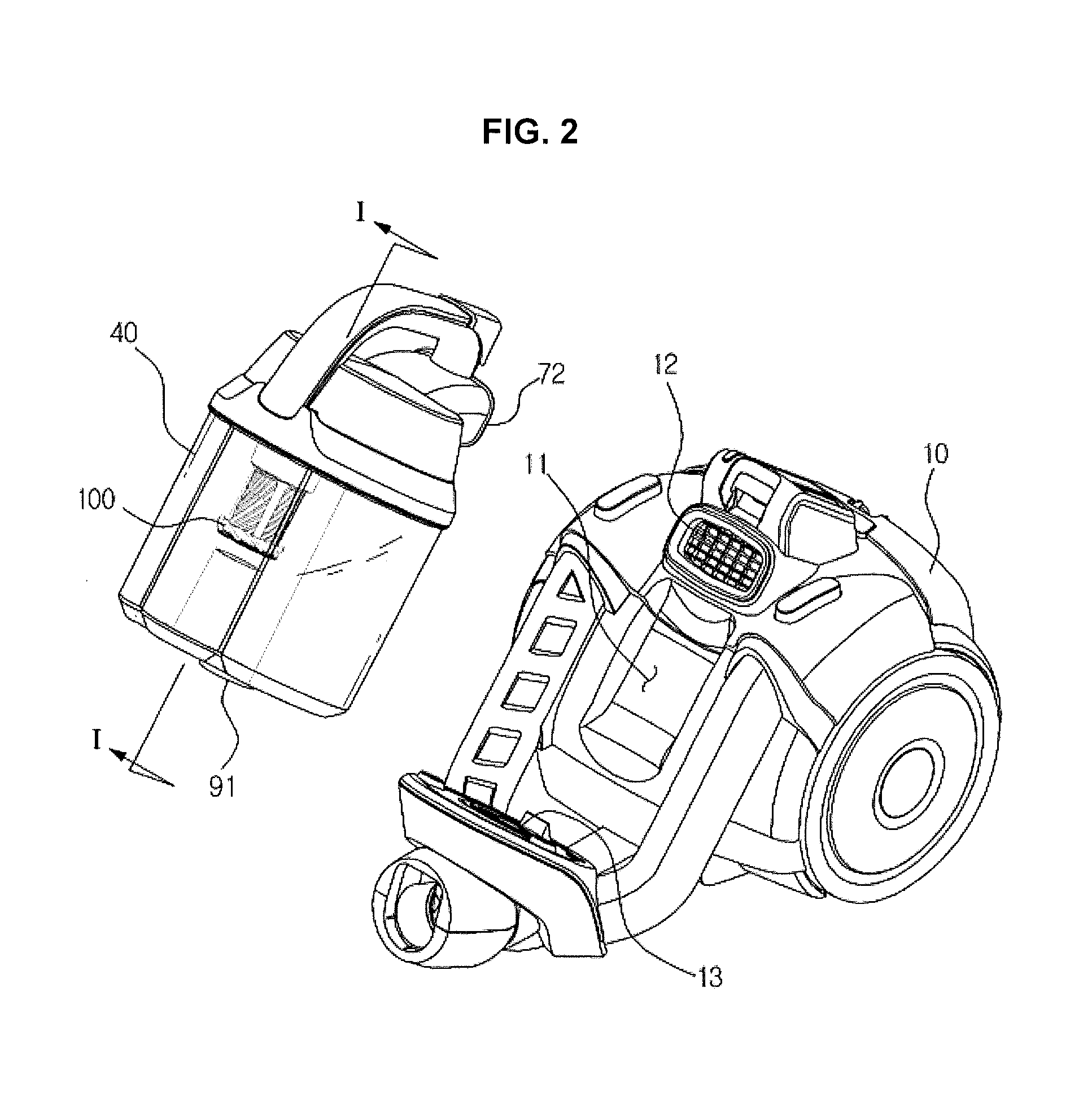
[0052]FIG. 1 is a view illustrating a vacuum cleaner according to an exemplary embodiment of the present invention, FIG. 2 is a view illustrating the vacuum cleaner of FIG. 1, in which the cyclone dust collector is separated from the main body.

[0053]Referring to FIGS. 1 and 2, the vacuum cleaner 1 of this embodiment includes a main body 10, a cyclone dust collector 40 mounted to the main body 10, and a suction part 21 to closely contact a surface to be cleaned to suction air.

[0054]The main body 10 is provided with a fan motor (not shown) to generate suction force. Air on a surface to be cleaned and dust contained in the air may be suctioned through the suction part 21 by the suction force generated by the main body 10. The suction part 21 may be formed to be wide and f...


PUM

PropertyMeasurementUnit
Forceaaaaaaaaaa
Diameteraaaaaaaaaa
Coloraaaaaaaaaa

Abstract

A cyclone dust collector includes a cyclone chamber to centrifugally separate dust by creating rotating airflow, and a ring-shaped indicator provided to the cyclone chamber to rotate due to the rotating airflow in the cyclone chamber. The indicator visualizes the rotating airflow by rotating when the rotating airflow is created. The user may easily check condition of the rotation airflow and take proper action in the case that the cleaner malfunctions.

Description

CROSS-REFERENCE TO RELATED APPLICATIONS[0001]This application claims the benefit of Korean Patent Application No. 2013-0067033, filed on Jun. 12, 2013 in the Korean Intellectual Property Office, the disclosure of which is incorporated herein by reference.BACKGROUND[0002]1. Field[0003]Embodiments of the present invention relate to a vacuum cleaner having a cyclone collector.[0004]2. Description of the Related Art[0005]A vacuum cleaner is a home appliance used to perform cleaning operation. The vacuum cleaner generally includes a fan motor to generate suction force, a suction part to suction air on a surface to be cleaned using suction force of the fan motor, and a dust collector to separate dust from the air suctioned through the suction part, collect the separated dust, and discharge purified air.[0006]A cyclone dust collector, which is a dust collector that separates dust from the suctioned air using centrifugal force, is widely used since it is semi-permanently usable and more hyg...

Claims


Application Information

Patent Timeline
IPC IPC(8): A47L9/19A47L9/16
CPCA47L9/16A47L9/19A47L9/2821
Inventor HAN, JUNG GYUNPARK, JOUNG SOOSO, DONG WONLIM, JONG GOOKJEON, KYONG HUI
Owner SAMSUNG ELECTRONICS CO LTD
Learn More