Pneumatic tire

a technology of pneumatic tires and pneumatic cylinders, which is applied in the direction of rolling resistance optimization, special tyres, vehicle components, etc., can solve the problems of reducing and affecting the service life of pneumatic tires. , to achieve the effect of suppressing the volume of conductive rubber, reducing uneven wear, and improving crack resistan

Active Publication Date: 2014-12-18
TOYO TIRE & RUBBER CO LTD
View PDF6 Cites 6 Cited by
  • Summary
  • Abstract
  • Description
  • Claims
  • Application Information

AI Technical Summary

Benefits of technology

[0009]As mentioned above, since the conductive part constituting the conductive path formed so as to connect the grounding surface and the lateral end surface or the bottom surface of the cap part passes through the inner portion of the cap part while avoiding the position covering the grounding surface, in the tire meridian cross section, it is possible to inhibit the conductive rubber which more easily wears in comparison with the non-conductive rubber from being exposed as the grounding surface to the surface, and it is possible to suppress the uneven wear such as the shoulder wear. Further, since the conductive rubber which is inferior in the crack resistance is configured so as to be retreated from the surface, it is possible to improve the crack resistance. Further, since the volume of the conductive rubber is suppressed while securing the conductive performance, it is also possible to improve the rolling performance.
[0010]For example, in the case where the lateral end site of the cap part is sectioned into the tire outer side and the tire inner side by the conductive rubber having the higher hardness than the hardness of the cap part, the rigidity of the lateral end site is enhanced in comparison with the case where the lateral end site is not sectioned, the cross section high order is suppressed, and the noise mainly in the high frequency area is reduced. On the other hand, in the case where the lateral end site of the cap part is sectioned into the tire outer side and the tire inner side by the conductive rubber having the lower hardness than the hardness of the cap part, the rigidity of the lateral end site becomes lower in comparison with the case where the lateral end site is not sectioned, a first order characteristic value is lowered, and the noise mainly in the low frequency area is reduced. Using this, the present invention has the conductive part having the extended site which extends to the outer side in the tire width direction, and thus the lateral end site of the cap part is sectioned into the tire inner and outer sides. Therefore, the rigidity of the lateral end site of the cap part can be set to a desired rigidity by being changed in comparison with the case where the conductive part is not provided, only by arranging the conductive part mentioned above, and the noise can be reduced through an appropriate rig...

Problems solved by technology

However, the rubber member has a problem that a defect such as a radio noise tends to be generated since an electric resistance is higher in comparison with a conventional pr...

Method used


Image

  • Pneumatic tire
  • Pneumatic tire
  • Pneumatic tire

Examples


example 1

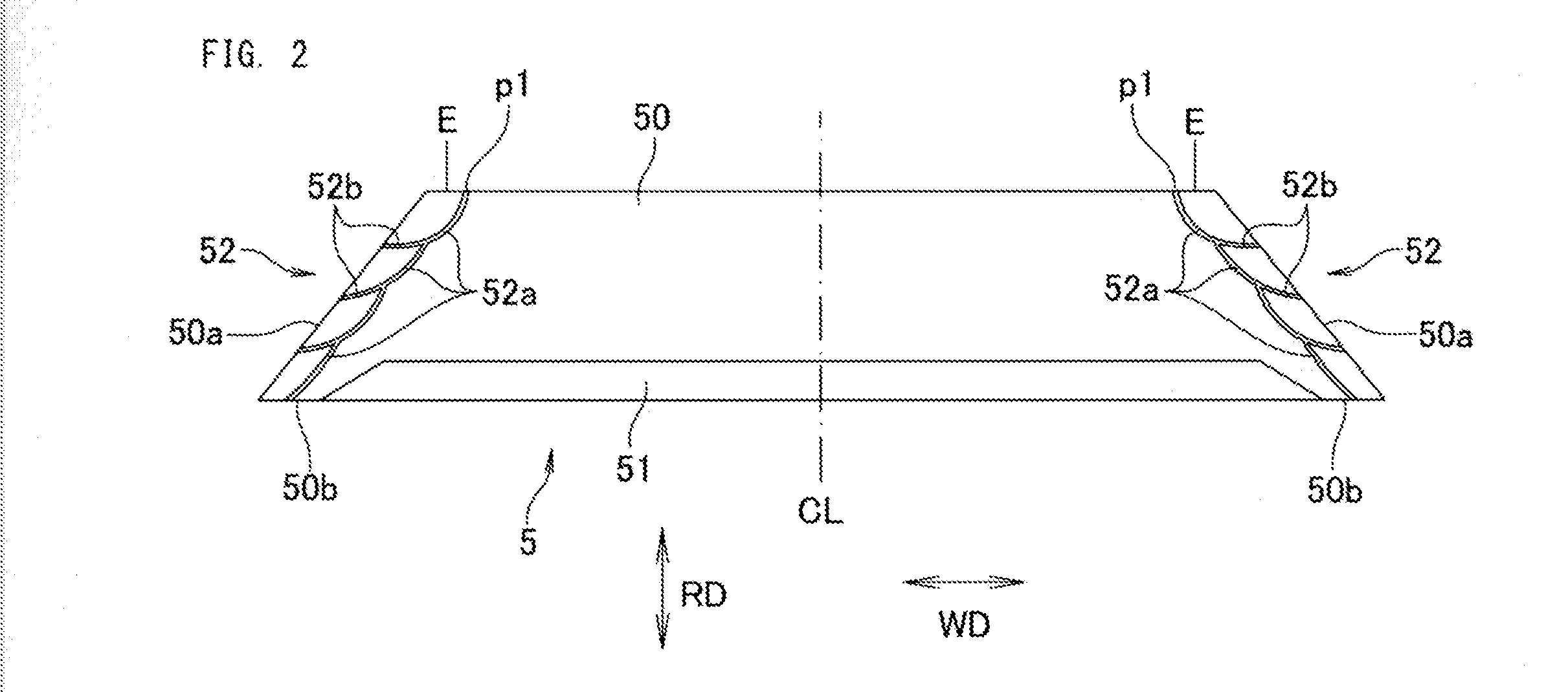
[0062]In relation to the tire according to the comparative example 1, the conductive part 52 was provided in the inner portions of both lateral wall sites of the cap part 50. The rubber hardness of the conductive part 52 was set to be lower than the rubber hardness of the cap part 50. The rest was set to the same as the tire according to the comparative example 1.

example 2

[0063]The conductive part 52 was provided only in the lateral end part in the inner side of the vehicle body among a pair of lateral end parts in both sides of the cap part 50 in the tire width direction WD. The rest was set to the same as the example 1.

example 3

[0064]The rubber hardness of the conductive part 52 was made higher than the rubber hardness of the cap part 50. The rest was set to the same as the example 1.

TABLE 1RubberHardnessLowHighhardnessofElectricfrequencyfrequencyPosition ofof conductiveresistanceRollingnoisenoiseUnevenCrackconductive partcap partrubber(MΩ)resistanceLFVlevellevelwearresistanceComparativeSurface of65563100100100100100100Example 1lateral end part of cap partBoth lateral endpartsExample 1Inner portion of6556310210510598105110lateral end part of cap partBoth lateral endpartsExample 2Inner portion of655631031001039998105lateral end part of cap partOnly one lateralend part (innerside of vehiclebody)Example 3Inner portion of5665310310598105105110lateral end part of cap partBoth lateral endparts

[0065]From Table 1, it is understood that the rolling resistance is effectively reduced in the examples 1 to 3 in comparison with the comparative example 1.

[0066]With regard to the current-applying performance, it is unders...


PUM


Abstract

An objective of the present invention is to provide a pneumatic tire whereby primarily rolling resistance is minimized and noise is minimized. This pneumatic tire tread rubber (5) comprises: a cap part (50) which is formed of non-conductive rubber and configures a grounding surface; a base part (51) which is disposed on the inner side of the cap part (50) in a tire radial direction (RD); and conductive parts (52) which are disposed in both of a pair of lateral end parts which are at ends of the cap (50) in a tire width direction, traverse the inner part of the cap (50) while avoiding a location which covers the grounding surface, and form shapes which connect the grounding surface with the bottom surface (50b) of the cap part (50) in the tire meridian cross-section. The conductive parts (52) are provided with extended sites (52b) which branch off outward to the tire width direction (WD) from conductive paths (52a) which connect the grounding surface with the bottom surface (50b) of the cap part (50). The conductive parts (52) are formed of a conductive rubber which has different rubber hardness from the non-conductive rubber which forms the cap part (50).

Description

TECHNICAL FIELD[0001]The present invention relates to a pneumatic tire which can discharge a static electricity generated in a vehicle body or the tire to a road surface.BACKGROUND ART[0002]In recent years, for the purpose of reducing a tire rolling resistance having a deep relationship with a fuel consumption performance, there has been proposed a pneumatic tire in which a rubber member such as a tread rubber is formed of a non-conductive rubber blended with a silica at a high rate. However, the rubber member has a problem that a defect such as a radio noise tends to be generated since an electric resistance is higher in comparison with a conventional product which is blended with a carbon black at a high rate, thereby inhibiting the discharge of the static electricity generated in the vehicle body or the tire to the road surface.[0003]Accordingly, there has been developed a pneumatic tire configured such that a current-applying performance can be achieved by arranging a conductive...

Claims


Application Information

Patent Timeline
IPC IPC(8): B60C19/08B60C1/00
CPCB60C1/0016B60C19/082B60C11/0058Y02T10/86
Inventor KAWAKAMI, KAZUKI
Owner TOYO TIRE & RUBBER CO LTD
Why Eureka
Try Eureka