High resolution light microscope

a light microscope, high-resolution technology, applied in the field of high-resolution light microscopes, can solve the problems of high optical path precision of the device, and time-consuming deflection of excitation light over the sample, so as to achieve better separation and better resolution

Active Publication Date: 2014-12-18
BRAUNSCHWEIG UNIVERSITY OF TECHNOLOGY
View PDF1 Cites 14 Cited by
  • Summary
  • Abstract
  • Description
  • Claims
  • Application Information

AI Technical Summary

Benefits of technology

[0025]Special preference is on an apparatus where the first and the second light source are linearly polarized, with the polarization of the de-excitation light beam having an angle of >0 to <180°, preferably 60° to 120°, in particular 90° to the polarization of the excitation light beam, e.g. by means of a polarization modulator located in their beam path. In this embodiment, only those fluorescent molecules are not de-excited whose transition dipole moment vectors exactly match the polarization of the excitation light beam so that the angle range of the suitably oriented fluorescent molecules is drastically reduced so that as a consequence individual molecules have a much better resolution and can be better distinguished.

Problems solved by technology

This process is disadvantageous in that the device requires an extremely high precision of optical path alignment for the excitation wavelength and for the de-excitation wavelength and a time-consuming deflection of excitation light over the sample, e.g. by means of a scanner.
This process is disadvantageous in that it is limited to those fluorescent molecules which are to be brought to an excitable state using a switching wavelength radiation, with time duration suitable for the analysis, and that the sequential irradiation and locating of the individual molecules is time consuming.

Method used


Image

  • High resolution light microscope
  • High resolution light microscope
  • High resolution light microscope

Examples


Embodiment Construction

[0037]The invention is now described in more details with reference to the figures that schematically show in

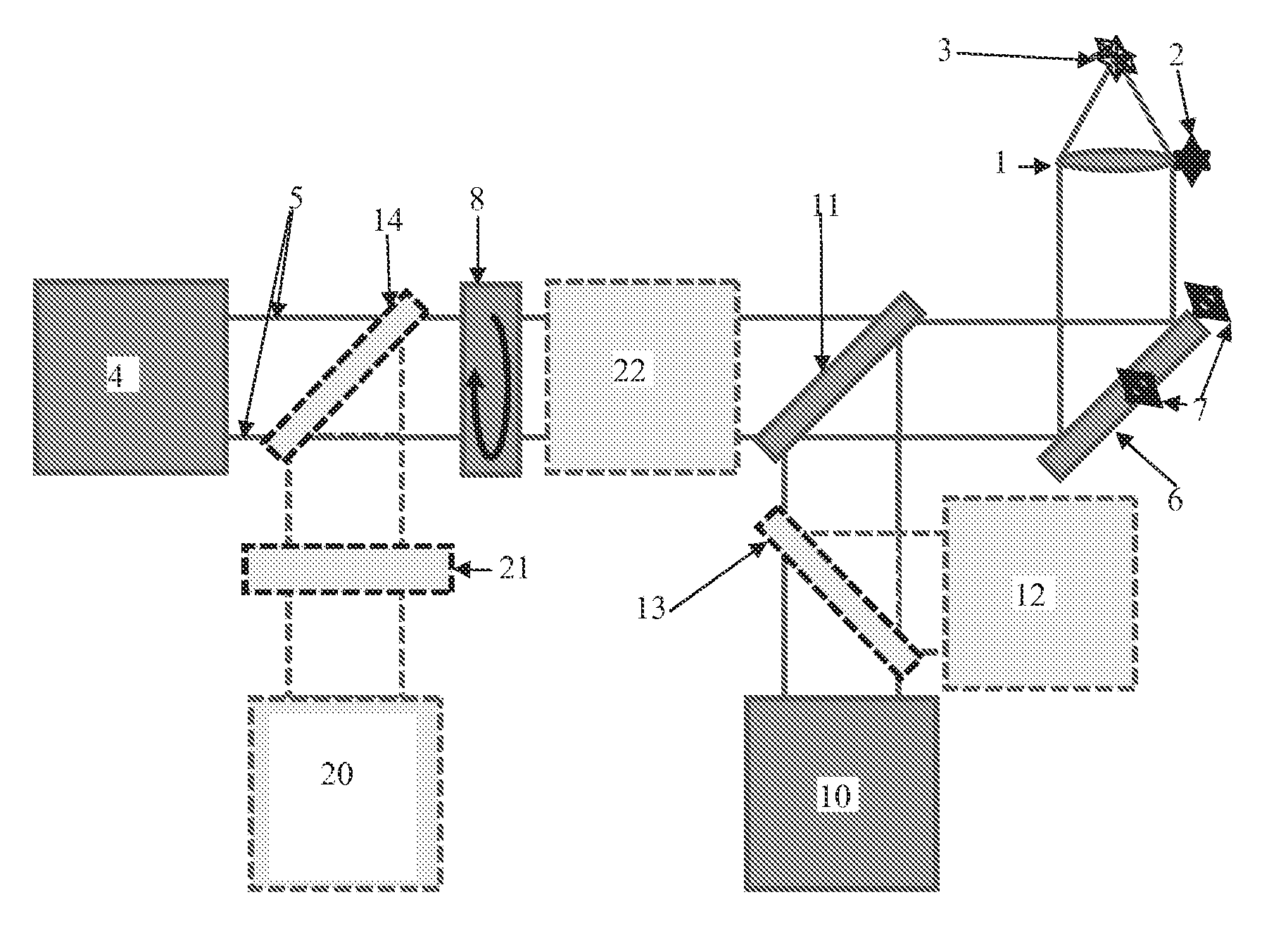
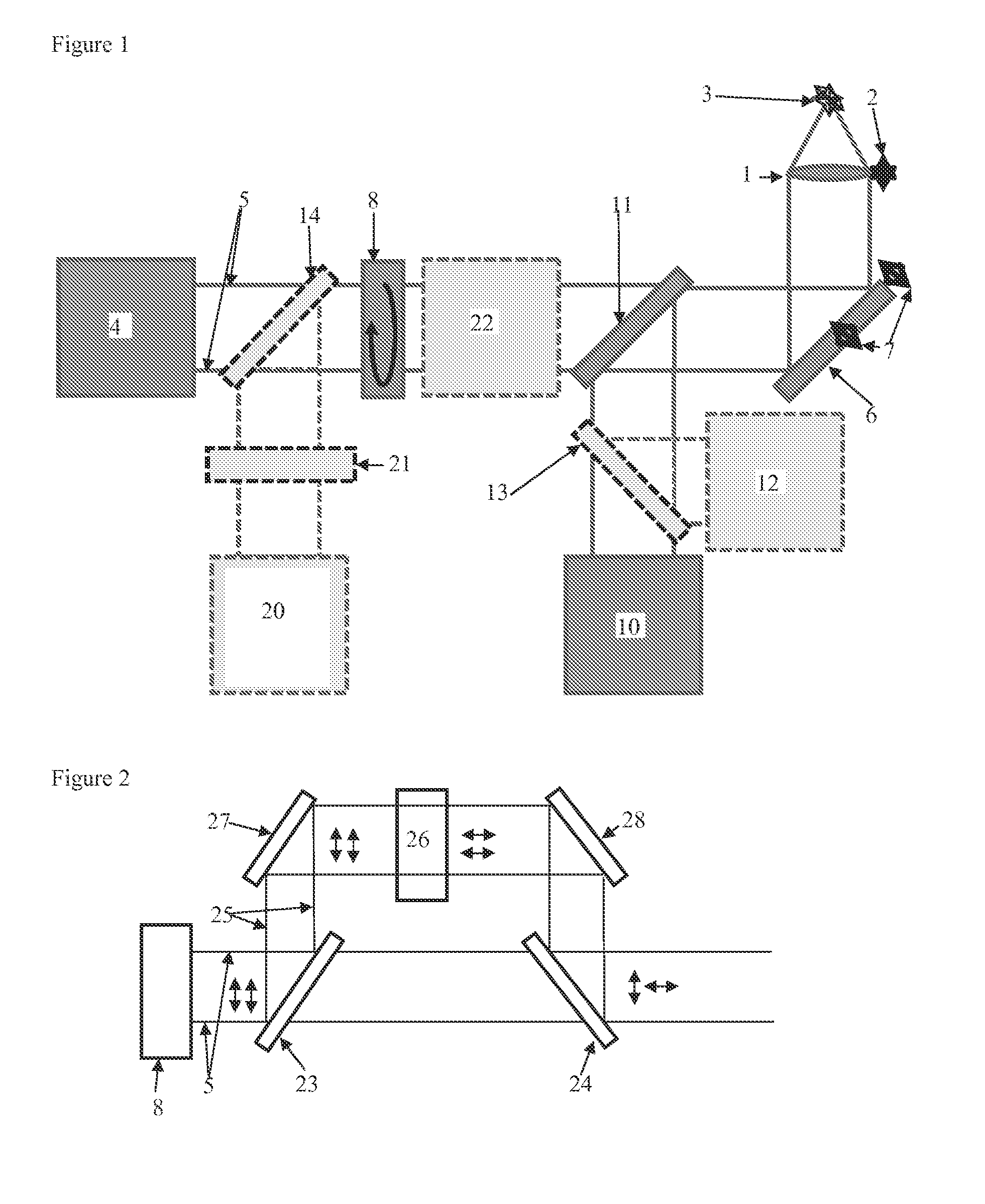
[0038]FIG. 1 an embodiment,

[0039]FIG. 2 a section of a preferred embodiment,

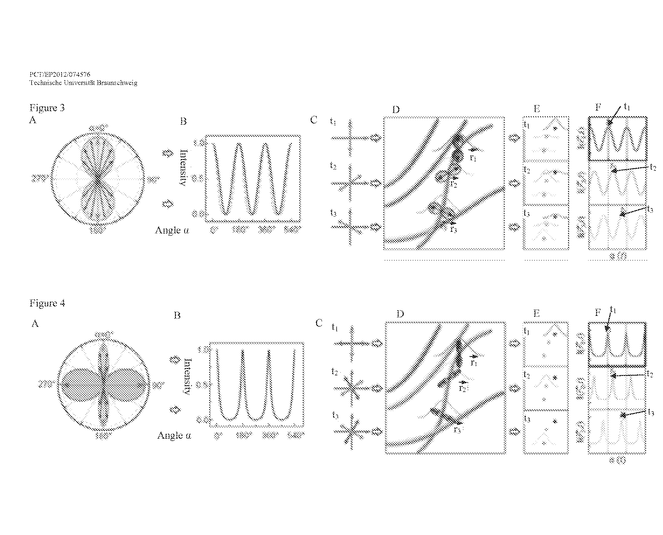
[0040]FIG. 3, A to F, the modulation and demodulation in an embodiment of the process with excitation light only,

[0041]FIG. 4, A to F, the modulation and demodulation in an embodiment of the process with excitation light and de-excitation light,

[0042]FIG. 5A a conventional fluorescence microscopic picture and in FIG. 5B a microscopic picture generated using the invention and in FIG. 5C superimposed intensity profiles of the same section through FIGS. 5A and 5B and

[0043]FIG. 6A a conventional fluorescence microscopic picture and in FIG. 6B another microscopic picture generated using the invention and in FIG. 6C superimposed intensity profiles of the same section through FIGS. 6A and 6B.

[0044]Using the focusing device 2, objective 1 can be focused on sample 3 which contains fluorescent molecules. An exc...


PUM

PropertyMeasurementUnit
angleaaaaaaaaaa
angleaaaaaaaaaa
angleaaaaaaaaaa

Abstract

The present invention relates to an apparatus for the optical analysis of a sample, also referred to as microscope, which is configured for an optical analysis process having high resolution for the detection of fluorescent molecules. The apparatus and the process applied when using the apparatus are configured for excitation light generated by an excitation light source to be directed onto a sample and the light emitted by the probe is detected. The apparatus and the process are characterized in that the excitation light is synchronized with the detection. The apparatus is characterized in that it has a polarization device which is configured to modulate the polarization of the excitation light with a modulation signal, wherein the modulation signal has or consists of at least one frequency, in particular a pre-determined frequency or several pre-determined superimposed frequencies, or the modulation signal consists of a sequence of signals that has no repetition.

Description

[0001]The present invention refers to an apparatus for the optical analysis of a sample, also referred to as microscope, which is configured for a high resolution optical analysis process for the detection of fluorescent molecules. The apparatus and the process applied by using the apparatus are arranged such that the excitation light generated by the excitation light source is focused on a sample and that the light emitted by the sample is detected. The apparatus and the process are characterized by the fact that the excitation light is synchronized with the detection. The excitation light source may consist of a laser device.STATE OF THE ART[0002]US2001 / 045523 describes the stimulated emission depletion microscopy (STED) which involves a sample being irradiated and sampled via a microscope objective by two parallel light paths, while light emitted by the sample exits through the same optical path and is detected. One of the light beams is coupled into the optical path by means of ...

Claims


Application Information

Patent Timeline
Patent Type & Authority Applications(United States)
IPC IPC(8): G01N21/64G02F1/01G02B21/16
CPCG01N21/6445G02B21/16G02F1/0136G01N2021/6463G02B27/141G02B26/06G02B27/283G02B21/0068G02B21/0076G01N21/6458G01N2021/6439
Inventor WALLA, PETER J.
Owner BRAUNSCHWEIG UNIVERSITY OF TECHNOLOGY
Why Eureka
Try Eureka