Charging Device for a Fuel Cell, in Particular of a Motor Vehicle

a charging device and fuel cell technology, applied in the direction of electrically induced generators, machines/engines, mechanical apparatus, etc., can solve problems such as unsatisfactory service life, and achieve the effects of low weight of charging devices, low axial forces, and efficient operation of charging devices

Inactive Publication Date: 2014-12-18
DAIMLER AG
View PDF7 Cites 19 Cited by
  • Summary
  • Abstract
  • Description
  • Claims
  • Application Information

AI Technical Summary

Benefits of technology

[0028]In another advantageous embodiment of the invention, the compressor wheel comprises compressor vanes for compressing the additional medium, in particular air, wherein the compressor vanes are curved forwards. This means that the compressor vanes are also curved in the direction of the rotational direction in which the compressor wheel rotates during the operation of the charging device. Thereby, the additional medium can be compressed in an efficient manner.
[0029]In another advantageous embodiment, the compensation element can be acted upon in a region of the compensation element by the outlet pressure prevailing downstream of the compressor wheel, wherein a chamber is delimited by means of said region, by means of the housing part and by means of at least two sealing elements of the charging device. As a result, the actions applied onto the compensation element by the inlet pressure and the outlet pressure do not influence each other such that the axial forces can be kept particularly low. This benefits the efficient operation of the charging device.
[0030]Here, the sealing elements are supported in each case, on the one hand, on the housing part and, on the other, on the compensation element or the turbine wheel or on the rotor shaft to which the turbine wheel and / or the compensation element are / is connected in a rotationally fixed manner. As a result, the required installation space and the weight of the charging device can be kept low, which results in a particularly efficient operation.
[0031]At least one of the sealing elements is formed as a piston ring for a piston of a reciprocating piston engine. This is beneficial for the low costs of the charging device. At least one of the sealing elements can also be formed as a non-contact seal, in particular as a labyrinth seal. This results in a small required installation space and also in low weight of the charging device according to the invention.
[0032]In order to implement a particularly efficient operation of the charging device, vane inlet angles of the impeller vanes are preferably greater than 100° and less than 150°. In combination with the particularly large aerodynamic embodiment of the turbine wheel in the inlet region thereof, this results in advantageous flow conditions for the waste gas.

Problems solved by technology

Such ball bearings, in particular in fast rotating rotors and at high axial forces and their fluctuations, have an unsatisfactory service life if no appropriate countermeasures are implemented.

Method used


Image

  • Charging Device for a Fuel Cell, in Particular of a Motor Vehicle
  • Charging Device for a Fuel Cell, in Particular of a Motor Vehicle
  • Charging Device for a Fuel Cell, in Particular of a Motor Vehicle

Examples


Embodiment Construction

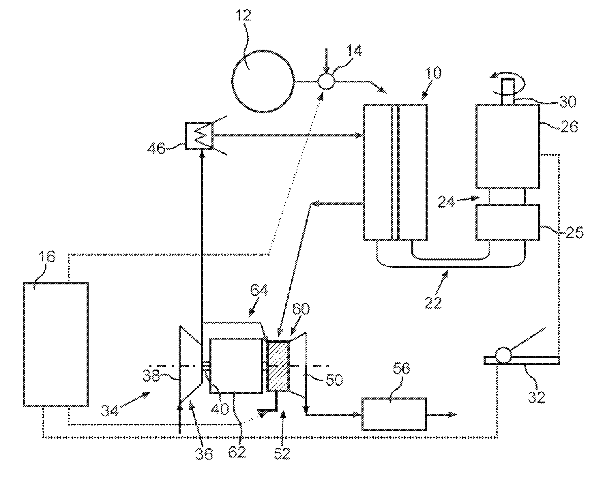
[0048]FIG. 9 shows a fuel cell 10 by means of which reaction energy of a continuously fed fuel and an oxidant can be converted into electrical energy. The fuel is present in the form of hydrogen, which is stored in a tank 12 and is fed to the fuel cell 10 via a fuel valve 14. The fuel valve 14 is controlled here by a control device 16. As an oxidant, the fuel cell 10 utilizes air from the surrounding area or oxygen as a constituent of this air, which is fed to the fuel cell.

[0049]The fuel cell 10 is connected, via lines 22, to a battery 25 that stores the produced electrical energy, which hereinafter is designated as current. The battery 25, in turn, is connected via lines 24 to an electric motor 26, which can be driven by the current stored in the battery 25. The electric motor 26 converts electrical energy into mechanical energy and delivers this energy in the form of a torque via a rotatable shaft 30. Thus, the fuel cell 10 serves for driving the electric motor 26 which, for exam...


PUM

PropertyMeasurementUnit
inlet angleaaaaaaaaaa
poweraaaaaaaaaa

Abstract

A charging device for a fuel cell includes a turbine having a housing part with a receiving chamber in which a turbine wheel of the turbine is received so as to be rotatable relative to the housing part about an axis of rotation. The turbine wheel includes impeller vanes via which a medium, in particular a gaseous waste gas of the fuel cell, can flow against the turbine wheel in an inlet region, and which are curved forwards at least in the inlet region.

Description

BACKGROUND AND SUMMARY OF THE INVENTION[0001]Exemplary embodiments of the present invention relate to a charging device for a fuel cell, in particular for a motor vehicle.[0002]German patent document DE 10 2010 026 909 A1 discloses a charging device for a fuel cell, wherein this fuel cell provides current for driving a motor vehicle by means of electric current, comprising a radial turbine having a housing part with a receiving chamber in which a turbine wheel of the turbine is received so as to be rotatable about an axis of rotation relative to the housing part. The turbine wheel comprises impeller vanes via which a medium, in particular a gaseous waste gas of the fuel cell, can flow against the turbine wheel in an inlet region.[0003]PCT patent document WO98 / 02643A1 discloses a charging device for a fuel cell, comprising an axial turbine which has a housing part with a receiving chamber in which a turbine wheel of the turbine is received so as to be rotatable about an axis of rotat...

Claims


Application Information

Patent Timeline
Patent Type & Authority Applications(United States)
IPC IPC(8): H01M8/04
CPCH01M2250/20H01M8/04111F01D3/00F02C6/12F05D2220/40Y02E60/50Y02T90/40
Inventor SUMSER, SIEGFRIEDKNOOP, ANDREASLOEFFLER, PAULSCHABEL, HANS-JORGSTEINHAUSER, BENJAMIN
Owner DAIMLER AG
Why Eureka
Try Eureka