
Software-defined energy communication networks

a technology of energy communication network and software, applied in the direction of electric variable regulation, process and machine control, instruments, etc., can solve the problems of lack of monitoring, high cost of copper wiring, and inability to support the internet in the massive datacenters of our homes, so as to facilitate the self-configuration of substation networks and facilitate the effect of additional functionality

Inactive Publication Date: 2014-12-18
UNIV OF COLORADO THE REGENTS OF
View PDF12 Cites 94 Cited by
  • Summary
  • Abstract
  • Description
  • Claims
  • Application Information

AI Technical Summary

Benefits of technology

The patent describes a new type of network for power grids that uses software to define which devices can communicate with each other. This allows for faster and more flexible management and control of the network. The network can adjust itself and handle different levels of automation, making it easier to manage and control distributed power sources. This technology can help improve the efficiency and resilience of power grids.

Problems solved by technology

Our society has become highly dependent on energy—without it, everything from the light and heat in our homes to the massive datacenters that support the Internet would not be possible.
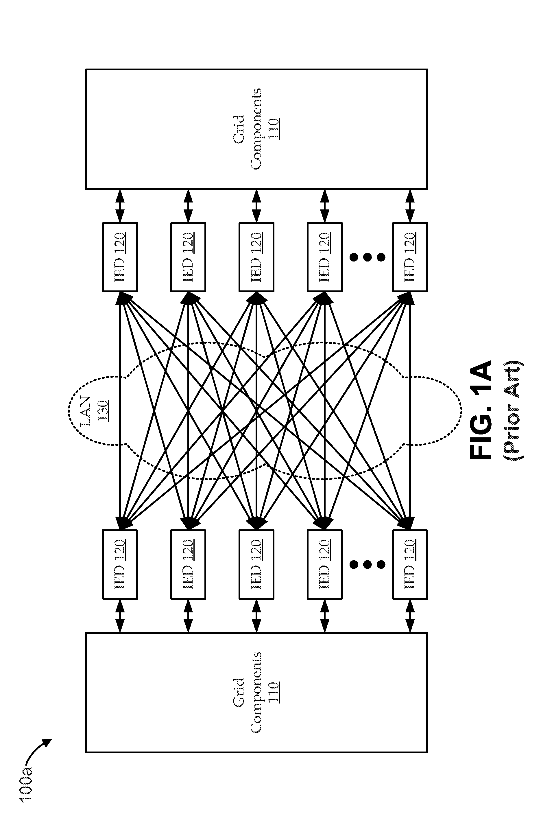
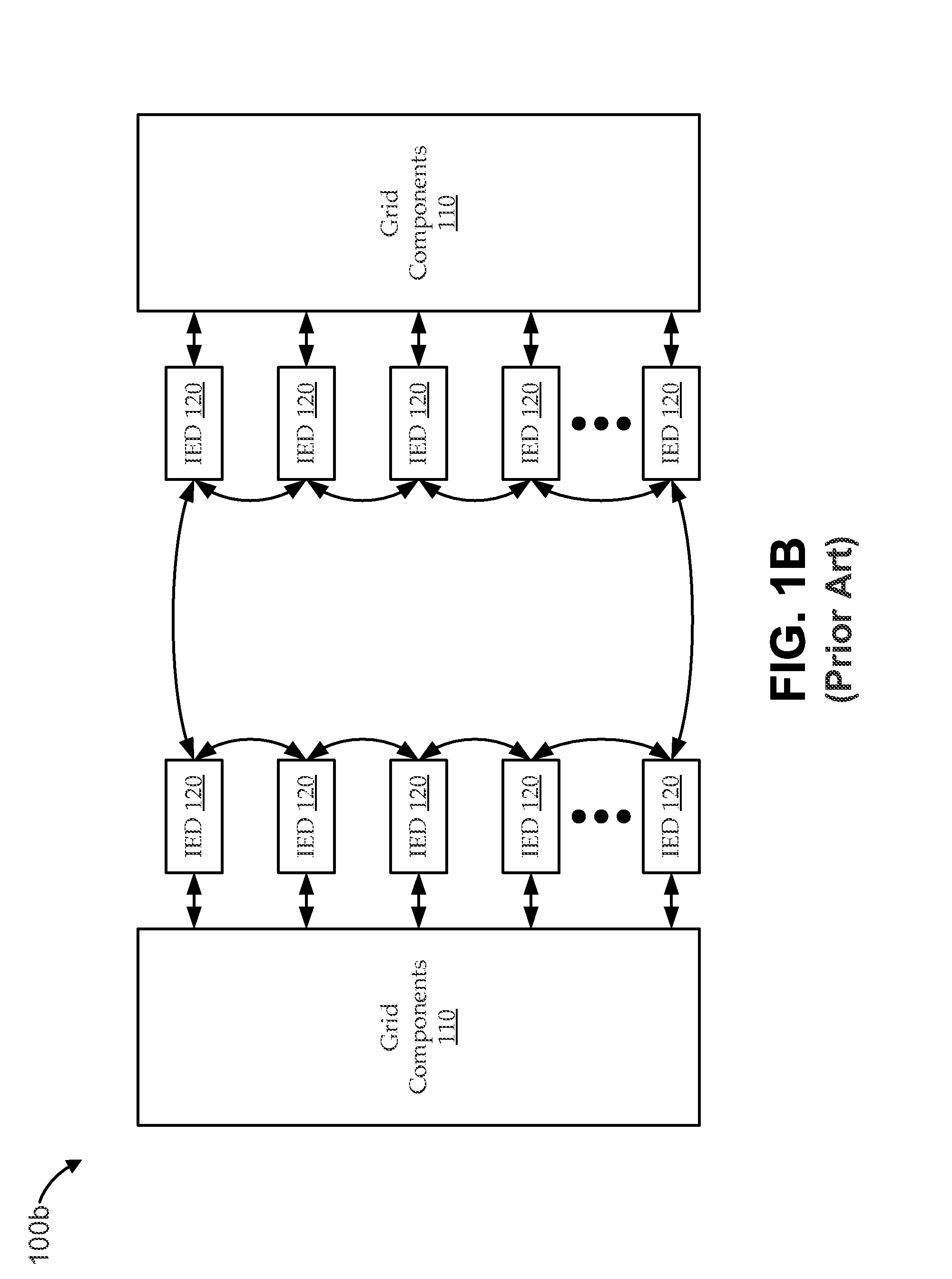
There were many disadvantages to this approach, including long implementation schedules, the high cost of copper wiring, the lack of monitoring, and the difficulty in performing maintenance.
While the transition to Ethernet is certainly an improvement, it still leaves many problems—namely, the long and arduous process to standardize each individual solution when introducing a new technology (stifling the ability to evolve as needs change) as well as the difficult and error-prone process to manage the network infrastructure.

Method used


Image

  • Software-defined energy communication networks
  • Software-defined energy communication networks
  • Software-defined energy communication networks

Examples


Embodiment Construction

[0016]In the following description, numerous specific details are set forth to provide a thorough understanding of various embodiments. However, one having ordinary skill in the art should recognize that the invention can be practiced without these specific details. In some instances, circuits, structures, and techniques have not been shown in detail to avoid obscuring the present invention. While a number of embodiments are described with specific reference to a “grid,” or the like, embodiments operate generally in context of any power network, including, for example, an electrical substation, a photovoltaic array, a wind farm, etc. Further, it will be understood that references to a “network,” or the like, are not intended to limit embodiments to any particular architecture. For example, similar techniques can be employed in context of public or private networks, wired or wireless links, cloud architectures, etc. Even further, reference to “intelligent electronic devices” or “IEDs...


PUM


Abstract

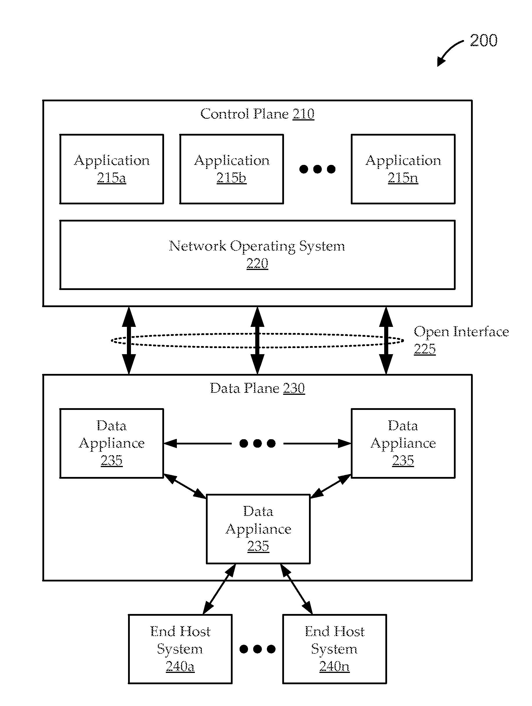
Systems and methods are described for software-defined approaches to energy communication networks (ECNs). For example, electrical substations typically host many Intelligent Electronic Devices (IEDs) that monitor and / or control the state of the substations' electricity infrastructures. Critical data from the IEDs can be packaged and transmitted between multiple IEDs for proper system monitoring and control. Even modern networks that interconnect IEDs tend to manifest many limitations, ranging from setup complexity to security policies. Embodiments use novel software-defined networking techniques to address these and other limitations. In some embodiments, power system requirements (e.g., data and communications requirements of IEDs) are translated into a set of networking requirements (e.g., as central routing tables). One implementation uses a Ryu-based, software-defined network controller. Embodiments provide features, such as auto-configuration, security management, re-routing, and flexibility to handle rapid evolution of the smart grid.

Description

FIELD[0001]Embodiments relate generally to energy infrastructures, and, more particularly, to software-defined energy communication networks for managing energy infrastructures.BACKGROUND[0002]Our society has become highly dependent on energy—without it, everything from the light and heat in our homes to the massive datacenters that support the Internet would not be possible. The electrical grid is the complex energy infrastructure that moves electricity from its sources of production (power plants) to its sources of consumption (load centers). The grid is comprised of the network of electrical transmission lines and substations that move energy from one source to another as well as data communication networks that transmit information about energy. These energy communication networks (ECNs) are pervasive and are the essential component in management of the grid.[0003]For more than 20 years, almost all communication between devices inside and outside of power substations has been im...

Claims


Application Information

Patent Timeline
IPC IPC(8): G05F1/66
CPCG05F1/66Y04S10/16Y04S10/18Y04S10/30H02J13/00002H02J13/00017H02J13/00034Y02E60/00Y04S40/124H02J13/00006Y04S40/12Y02B90/20
Inventor KELLER, ERICCAHN, ADAM J.PAREJA, JUAN ESTEBAN HOYOSHULSE, MATTHEW
Owner UNIV OF COLORADO THE REGENTS OF
Learn More