
Failure detection in high-performance clusters and computers using chaotic map computations

a clustering and computation technology, applied in the field of failure detection, can solve problems such as system failure in many ways, complex task of detecting processor faults, and increase in complexity

Active Publication Date: 2014-12-18
UT BATTELLE LLC
View PDF4 Cites 7 Cited by
  • Summary
  • Abstract
  • Description
  • Claims
  • Application Information

AI Technical Summary

Benefits of technology

The patent describes a system for detecting and diagnosing faults in multi-processor machines, such as high-performance clusters and supercomputers. The system uses chaotic map computations and memory sweeps to detect errors caused by processor cores, memory elements, and interconnections. The system can identify and locate errors quickly, allowing for corrective measures to be taken before they negatively impact the performance of the machine. The technical effect of the patent is to provide a reliable and efficient way to detect and diagnose faults in complex computing systems, improving their reliability and resilience.

Problems solved by technology

The task of detecting processor faults is complicated and increases in complexity as processors are added to computing systems.
Due to the complexities of these architectures and the large number of components, the systems may fail in many ways including when Arithmetic and Logic Units (ALUs), memory elements, transport components, etc. fail.
Some failures are difficult to detect at the node and the board level, and consequently do not allow for corrective measures such as check point recovery or process migration, when failures occur.
When software is executed repeatedly, faults can negatively influence the results, leading to different outputs for the same input.
Repeated execution of existing application codes with known outputs for diagnosis purposes can require significant execution times and is not always capable of detecting many errors, including errors at the board or node level.

Method used


Image

  • Failure detection in high-performance clusters and computers using chaotic map computations
  • Failure detection in high-performance clusters and computers using chaotic map computations
  • Failure detection in high-performance clusters and computers using chaotic map computations

Examples


Embodiment Construction

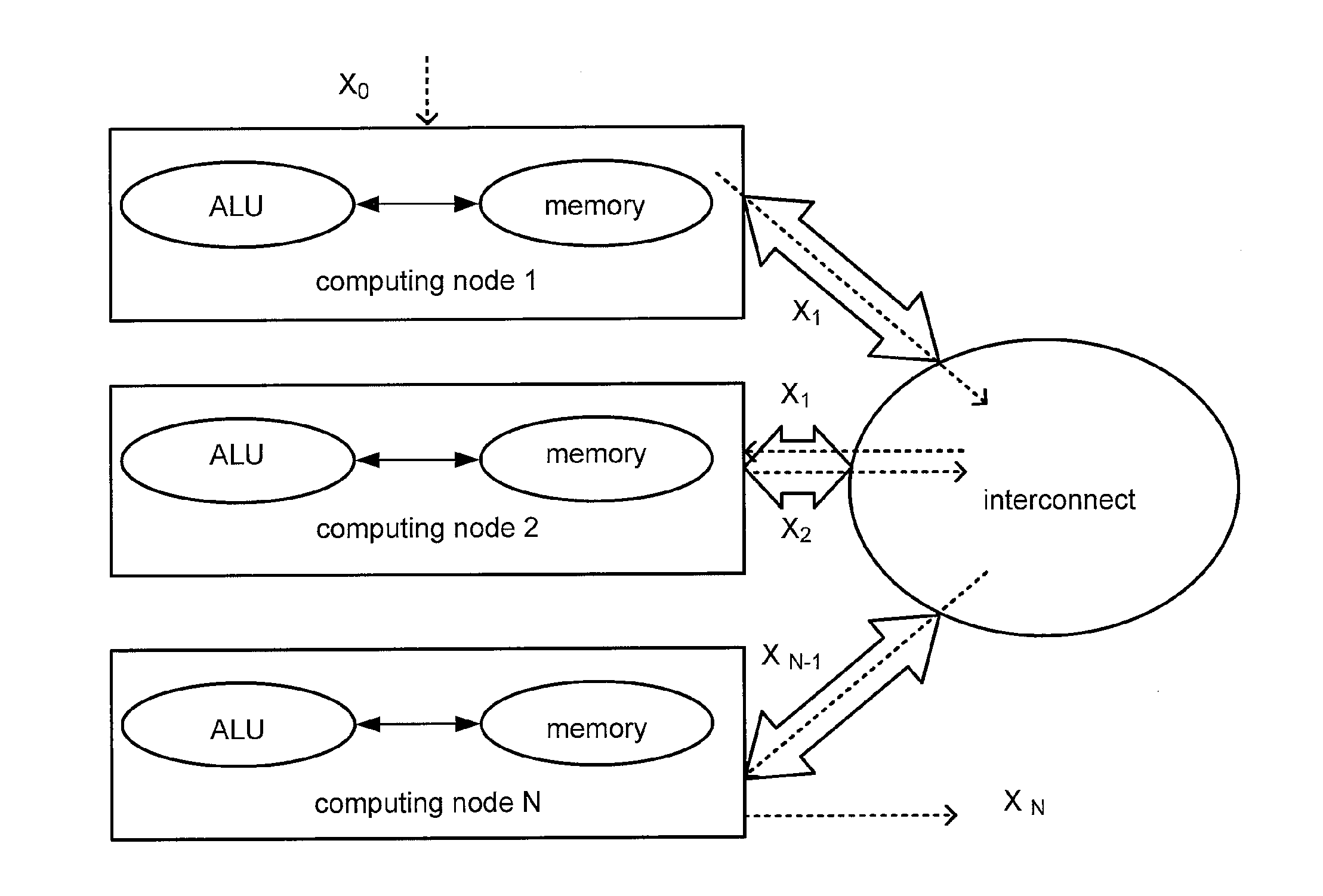
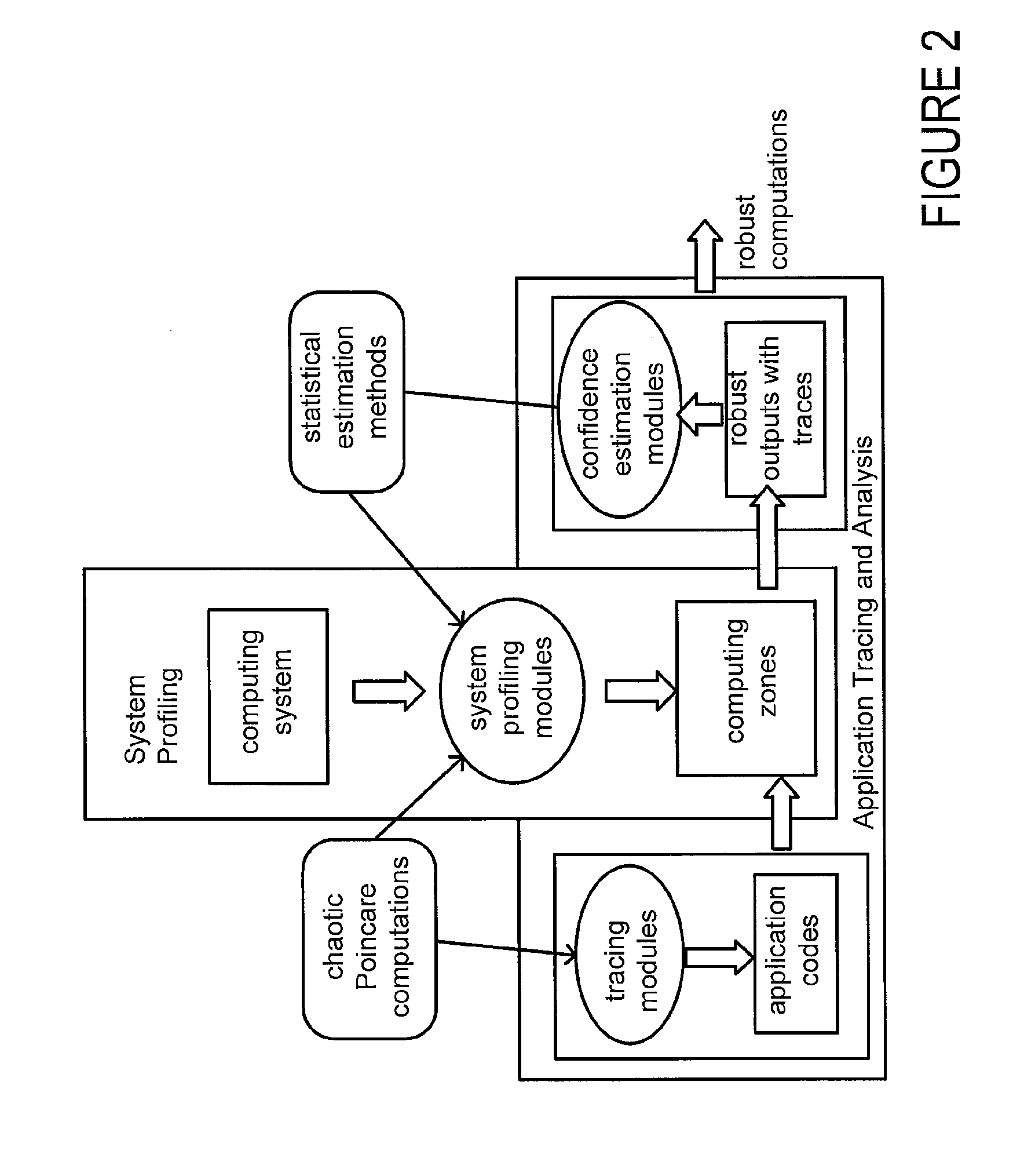
[0020]This disclosure discloses technology that rapidly diagnoses faults in multi-processor machines, such as high-performance clusters and supercomputers. Through the execution of multiple concurrent threads and memory transfer operations, the failure detection systems and processes (referred to as systems or failure detection systems) detect a wide class of errors including errors caused by failures in one or more processors, one or more memory elements, and one or more interconnections. The failure detection systems use dedicated threads to execute chaotic map computations and in some applications, execute memory sweeps and global-local memory movements from node-to-node. The chaotic map threads generate identical state (or nearly identical) trajectories when there are no faults. Under failures they generate divergent trajectories through multiple processor cores, memory elements, and / or interconnects in time and state within a few software code iterations that may be detected th...


PUM


Abstract

A programmable media includes a processing unit capable of independent operation in a machine that is capable of executing 1018 floating point operations per second. The processing unit is in communication with a memory element and an interconnect that couples computing nodes. The programmable media includes a logical unit configured to execute arithmetic functions, comparative functions, and / or logical functions. The processing unit is configured to detect computing component failures, memory element failures and / or interconnect failures by executing programming threads that generate one or more chaotic map trajectories. The central processing unit or graphical processing unit is configured to detect a computing component failure, memory element failure and / or an interconnect failure through an automated comparison of signal trajectories generated by the chaotic maps.

Description

STATEMENT REGARDING FEDERALLY SPONSORED RESEARCH AND DEVELOPMENT[0001]This invention was made with United States government support under Contract No. DE-AC05-00OR22725 awarded to Oak Ridge National Laboratory by the United States Department of Energy. The United States government has certain rights in the invention.BACKGROUND[0002]1. Technical Field[0003]This disclosure relates to failure detection and more particularly to fault detection of computing machines that utilize multiple processor cores and accelerators.[0004]2. Related Art[0005]The task of detecting processor faults is complicated and increases in complexity as processors are added to computing systems. As more processors are added, more sockets, layers of memory, memory buses, HyperTransport (HT) links, and other components are needed. Due to the complexities of these architectures and the large number of components, the systems may fail in many ways including when Arithmetic and Logic Units (ALUs), memory elements, tr...

Claims


Application Information

Patent Timeline
Patent Type & Authority Applications(United States)
IPC IPC(8): G06F11/07
CPCG06F11/079G06F11/0709G06F11/3006G06F11/3447
Inventor RAO, NAGESWARA S.
Owner UT BATTELLE LLC
Learn More