
Bottom plate structure for installing faucet

a faucet and bottom plate technology, applied in the field of faucets, can solve the problems of reducing the service life of the faucet, and reducing the material waste during production, so as to reduce the waste of materials during production, reduce the production cost, and simplify the manufacturing process

Inactive Publication Date: 2014-12-25
XIAMEN RUNNER IND CORP
View PDF6 Cites 0 Cited by
  • Summary
  • Abstract
  • Description
  • Claims
  • Application Information

AI Technical Summary

Benefits of technology

The present invention provides a bottom plate structure for installing a faucet that simplifies the production process, saves material, and reduces production cost. This is achieved by bonding the bottom plate and filling strip together using over-molding, which eliminates the need for manual gluling. The filling strip is also made in a long strip shape, which reduces material waste during production.

Problems solved by technology

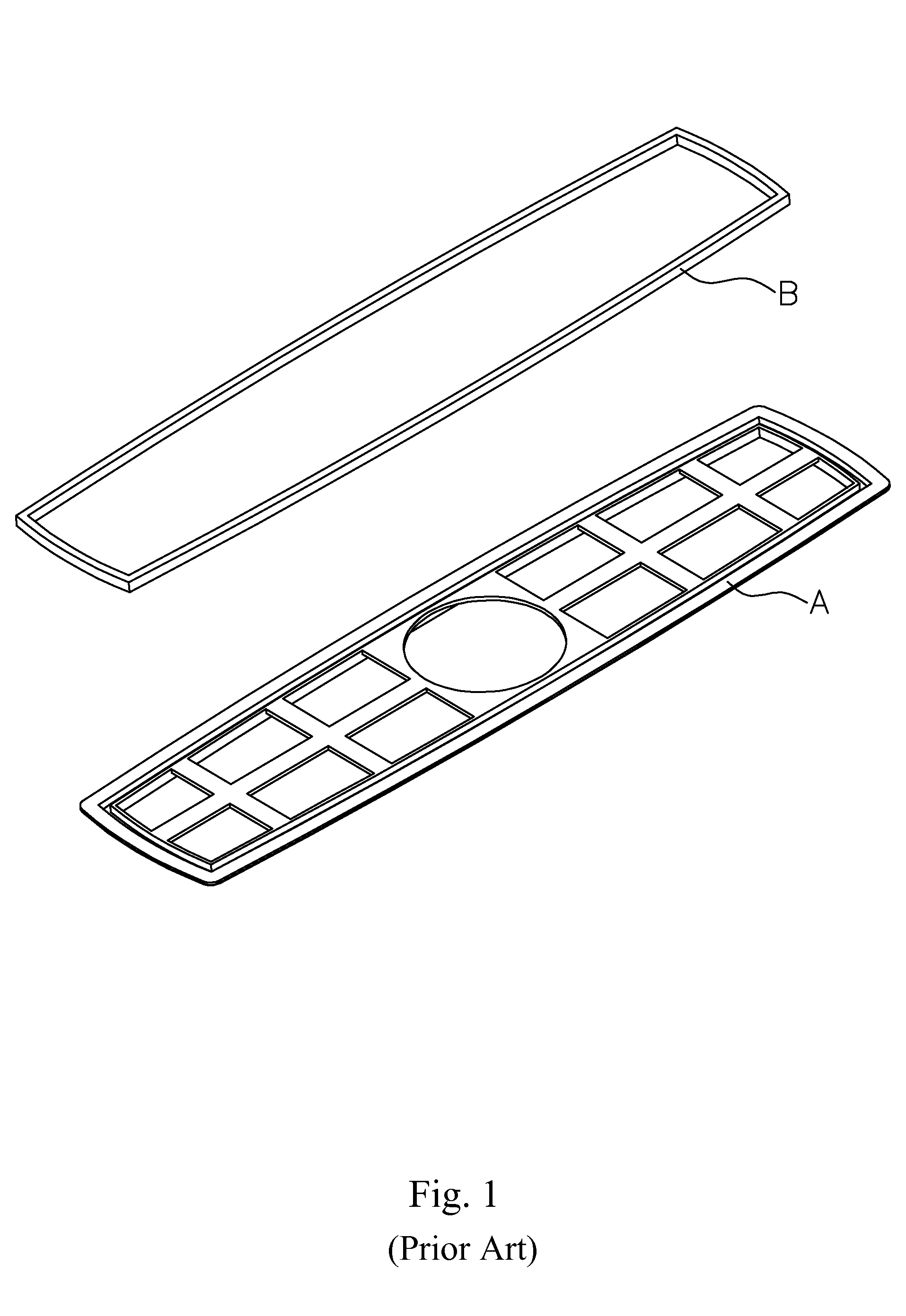
Wherein, the gluing process is done manually, so that the production cost remains rather high.
Also, the washer B glued onto the bottom plate A tends to detach easily when it is immersed in water for a long period of time.
Moreover, the washer B is produced by cutting it from a whole planar plate depending on actual requirement, thus the remains of the planar plate are discarded, to cause waste of material and problem of pollution.
Therefore, presently, the design and performance of the bottom plate for a faucet is not quite satisfactory, and it has much room for improvement.

Method used


Image

  • Bottom plate structure for installing faucet
  • Bottom plate structure for installing faucet
  • Bottom plate structure for installing faucet

Examples


Embodiment Construction

[0018]The purpose, construction, features, functions and advantages of the present invention can be appreciated and understood more thoroughly through the following detailed description with reference to the attached drawings.

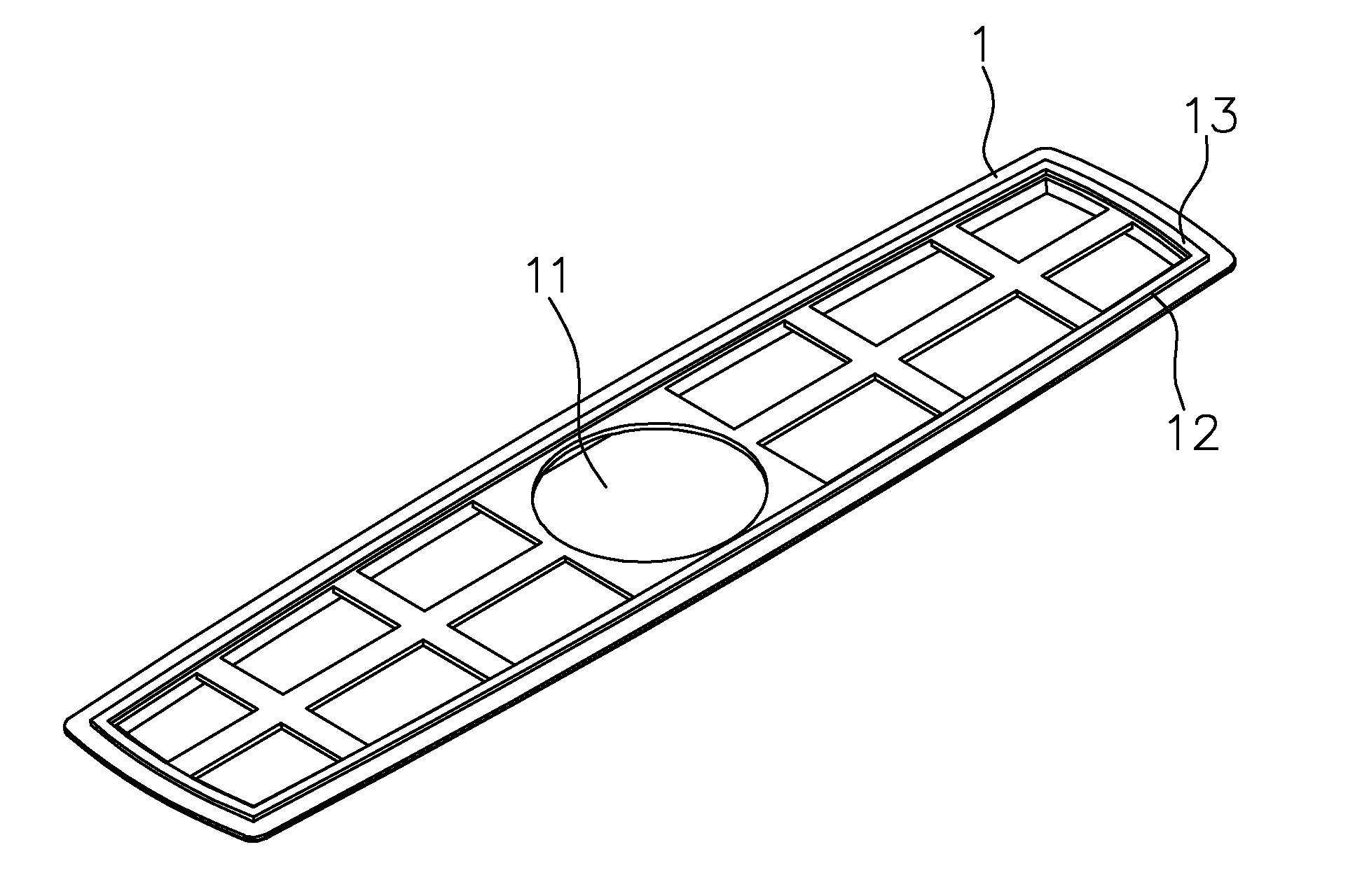
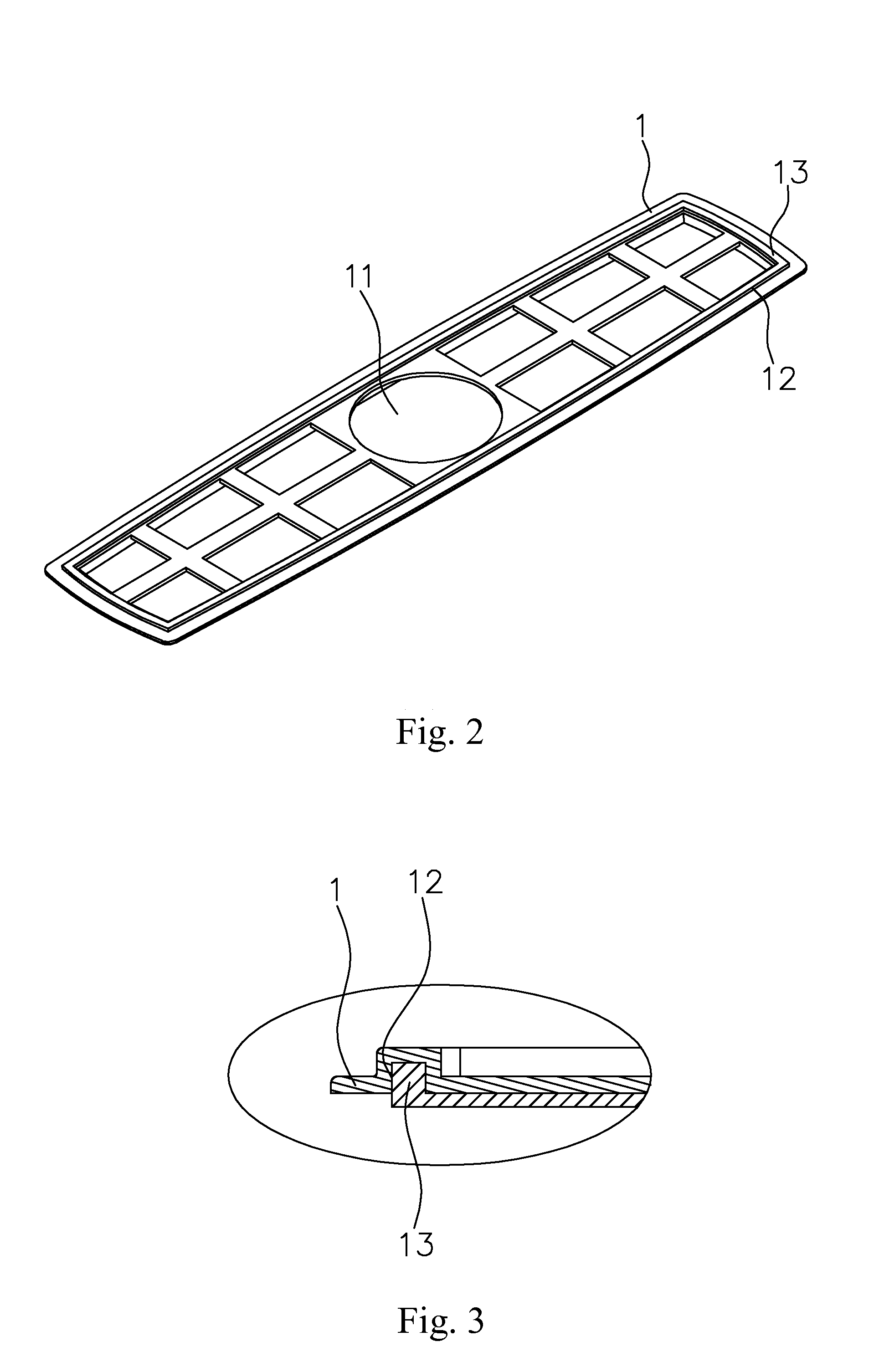
[0019]Refer to FIGS. 2 and 3 respectively for a schematic diagram of structure of a bottom plate used for installing a faucet according to the present invention, and a cross section view of a portion of structure of a bottom plate used for installing a faucet according to the present invention. As shown in FIGS. 2 and 3, the present invention provides a bottom plate structure used for installing a faucet, including: a bottom plate 1; an indent slot 12; and a filling strip 13. Wherein, the bottom plate 1 is formed by using low density polyethylene (LDPE) material, and similar to the prior art, the center of the bottom plate 1 is provided with an installation hole 11. In order to save material, the bottom plate 1 can adopt a hollow structure. The unique feature o...


PUM


Abstract

A bottom plate structure used for installing a faucet, includes: a bottom plate, with its center provided with an installation hole; an indent slot, formed around perimeter of surface of said bottom plate; and a filling strip, which is of a long strip shape, placed into said indent slot, to form integrally together through over-molding.

Description

BACKGROUND OF THE INVENTION[0001]1. Field of the Invention[0002]The present invention relates to a faucet, and in particular to a bottom plate structure used for installing a faucet.[0003]2. The Prior Arts[0004]Presently, in installing a faucet, the bottom plate A and slippery-proof washer B are formed separately, and then they are glued together by using glue, as shown in FIG. 1. Wherein, the gluing process is done manually, so that the production cost remains rather high. Also, the washer B glued onto the bottom plate A tends to detach easily when it is immersed in water for a long period of time. Moreover, the washer B is produced by cutting it from a whole planar plate depending on actual requirement, thus the remains of the planar plate are discarded, to cause waste of material and problem of pollution.[0005]Therefore, presently, the design and performance of the bottom plate for a faucet is not quite satisfactory, and it has much room for improvement.SUMMARY OF THE INVENTION[0...

Claims


Application Information

Patent Timeline
Patent Type & Authority Applications(United States)
IPC IPC(8): E03C1/04
CPCE03C1/0401
Inventor HONG, HAI-BO
Owner XIAMEN RUNNER IND CORP
Learn More