Stepper motor with integrated brake and drive circuit

Inactive Publication Date: 2014-12-25
JOHNSON ELECTRIC INTERNATIONAL AG
View PDF9 Cites 8 Cited by
  • Summary
  • Abstract
  • Description
  • Claims
  • Application Information

AI Technical Summary

Benefits of technology

[0018]Embodiments of the present invention provide a stepper motor with integrated power-off solenoid brake having a simple electronics. A power-off s

Problems solved by technology

In prior art stepper motor actuators a holding torque is usually realized by means of mechanical friction such as a self locking transmission gear with low efficiency, or magnetic detent torque.
These mechanisms reduce the available output torque or introduce electromagnetic torque ripple with negative consequences for low-vibration dynamic operation.
Therefore, they are in conflict with the requirement of an efficient electromagnetic actuator system as currently

Method used


Image

  • Stepper motor with integrated brake and drive circuit
  • Stepper motor with integrated brake and drive circuit
  • Stepper motor with integrated brake and drive circuit

Examples


Embodiment Construction

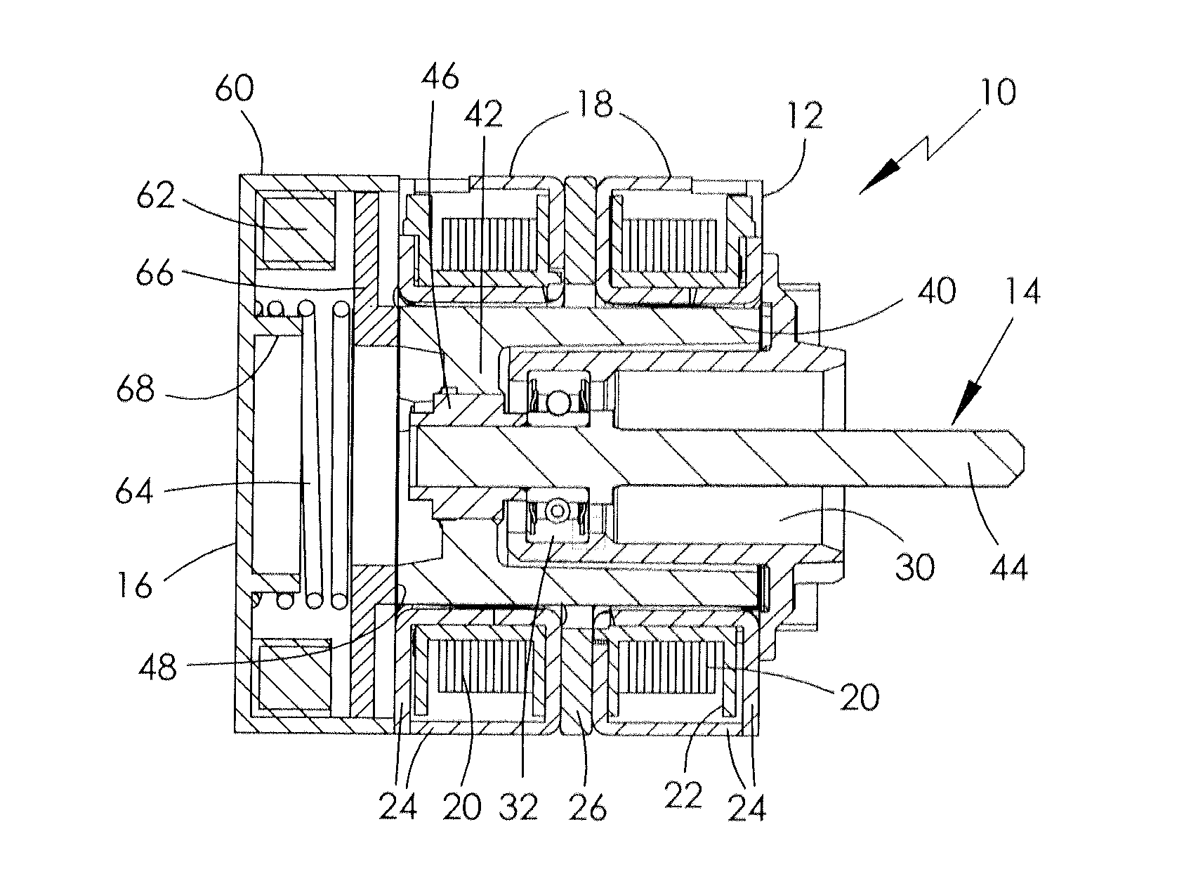
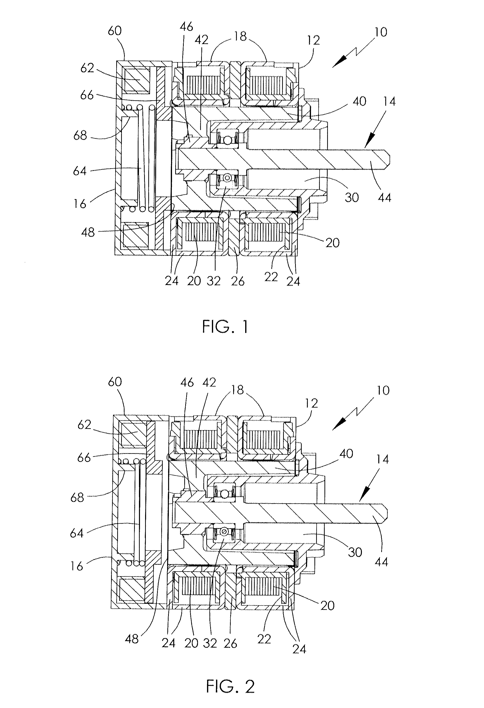
[0028]FIG. 1 is a sectional view of a two-phase stepper motor 10 with an electromagnetic brake attached to the left hand side. The stepper motor is shown in schematic form to illustrate the principle of operation of the invention. As such not all components of the motor are shown, such as motor terminals, bearings, housing and mounting structures. The stepper motor has a stator 12, a rotor 14 and the electromagnetic brake in the form of a solenoid brake 16. The stator 12 has two phase assemblies 18, each comprising a coil 20 wound on a bobbin 22 and disposed between a pair of pole plates 24. The two phase assemblies are separated axially by a spacer 26.

[0029]The phase assemblies define an internal space in which the rotor 14 is located. The rotor comprises a rotor core 40 and a shaft 44. The shaft is fixed to a hub 42 of the rotor core by a coupling 46. The rotor core is preferably a molded permanent magnet but may be of another form such as a supporting core, including the hub havi...


PUM


Abstract

A stepper motor has a rotor, a stator and an electro-magnetic brake. The rotor has permanent magnet rotor poles. The stator has a stator winding with at least 2 phases. The brake is electrically connected to the phases of the stator winding and arranged to be released when at least one of the phases is energized.

Description

CROSS REFERENCE TO RELATED APPLICATIONS[0001]This non-provisional patent application claims priority under 35 U.S.C. §119(a) from Patent Application No. 1311035.8 filed in the United Kingdom on Jun. 20, 2013, the entire contents of which are hereby incorporated by reference.FIELD OF THE INVENTION[0002]This invention relates to a stepper motor and in particular, to a stepper motor having an integrated brake.BACKGROUND OF THE INVENTION[0003]Stepper motors are used in precise positioning applications. In order to temporarily hold the target position a holding torque with reduced or no electrical input power is desirable for low heat dissipation and low power consumption.[0004]In prior art stepper motor actuators a holding torque is usually realized by means of mechanical friction such as a self locking transmission gear with low efficiency, or magnetic detent torque. These mechanisms reduce the available output torque or introduce electromagnetic torque ripple with negative consequence...

Claims


Application Information

Patent Timeline
IPC IPC(8): H02K7/102H02K37/14
CPCH02K37/14H02K7/1025H02K37/24H02P8/24H02P8/30H02P15/00
Inventor FURLAN, MIHA
Owner JOHNSON ELECTRIC INTERNATIONAL AG
Why Eureka
Try Eureka