Electrical machine

a technology of electric motors and electric motors, applied in the direction of magnetic circuits characterised by magnetic materials, magnetic circuit shapes/forms/construction, magnetic circuit rotating parts, etc., can solve the problems of increasing cost-intensive so-called rare earth elements (hree), such as terbium and particularly dysprosium, and achieve high demagnetization resistance, low price, and production special

Inactive Publication Date: 2014-12-25
BROSE FAHRZEUGTEILE GMBH & CO KG HALLSTADT (DE)
View PDF1 Cites 16 Cited by
  • Summary
  • Abstract
  • Description
  • Claims
  • Application Information

AI Technical Summary

Benefits of technology

[0008]It is therefore an object of the invention to provide an especially suitable electrical machine, which can be produced especially at a relatively low price and advantageously has a relatively high demagnetization resistance.
[0009]In an embodiment, the electrical machine can be an electric motor, preferably a brushed DC motor, and comprises a stator and a rotor. The rotor is mounted rotatably around an axis of rotation with respect to the stator, whereby the rotor is disposed, for example, within the stator. Alternatively, the rotor surrounds the stator in the manner of an external rotor. The stator and rotor are suitably disposed within a housing, which protects both of these from possible damage and / or environmental effects.

Problems solved by technology

Because both high operating temperatures and (external) magnetic fields, which are caused, for example, by current peaks induced in the stator-side field winding or coil, can lead to an undesirable end demagnetization of the rotor-side permanent magnet, magnet materials or alloys with as high a coercive field strength as possible are usually used.
In the meantime, however, the so-called heavy rare earth elements (HREE) such as, for example, terbium and particularly dysprosium, have become increasingly cost-intensive.

Method used


Image

  • Electrical machine
  • Electrical machine
  • Electrical machine

Examples


first embodiment

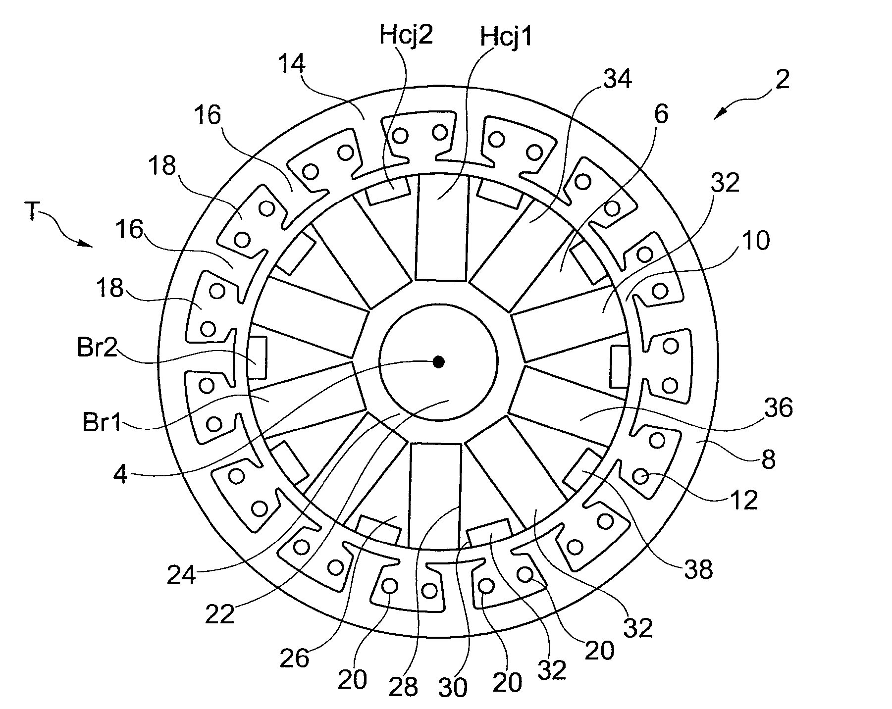
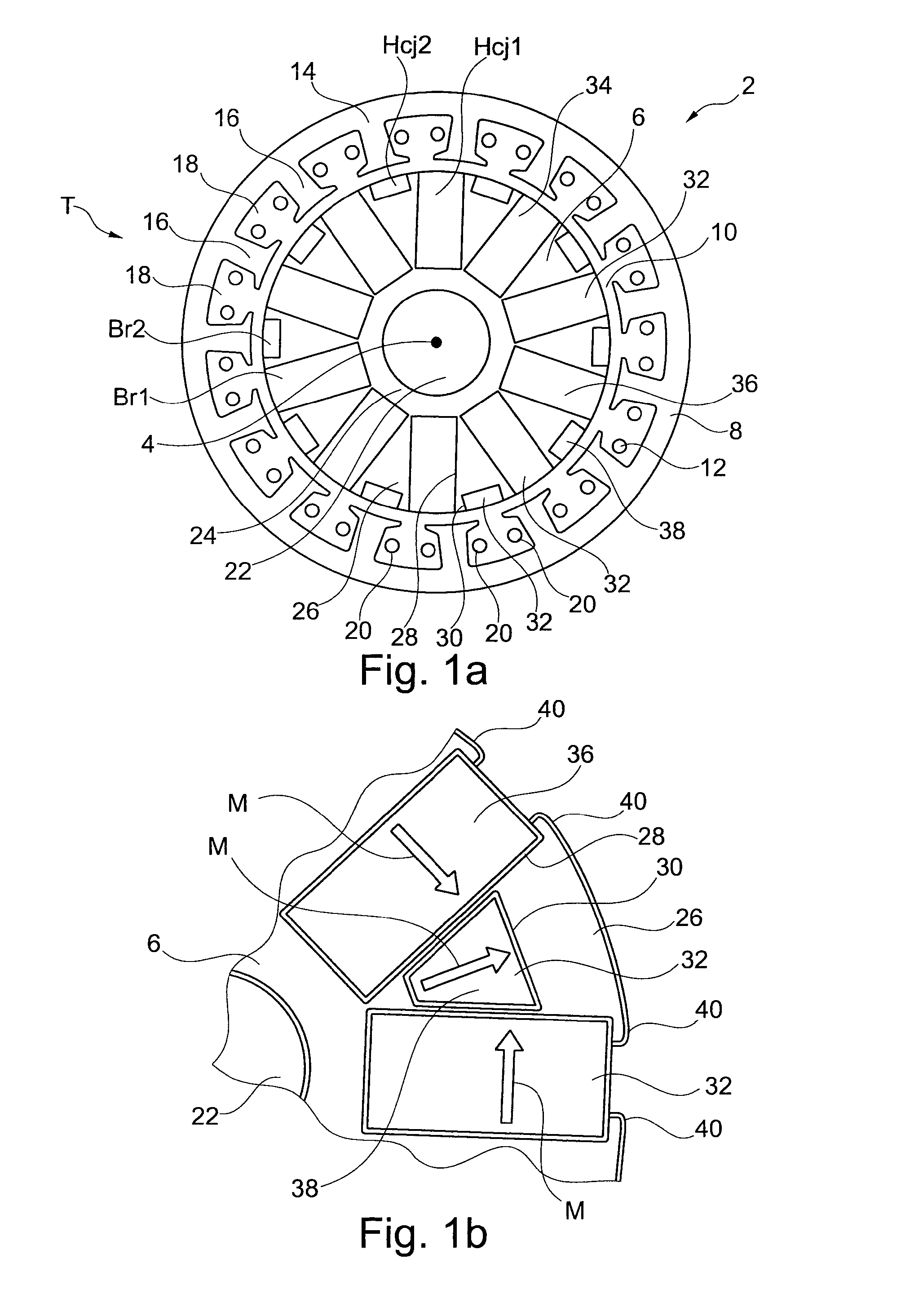
[0047]an electrical machine 2, designed as a synchronous machine and used as an electric motor, is shown in FIG. 1a. Electrical machine 2 is shown here in a sectional illustration perpendicular to an axis of rotation 4 of a rotor 6, which is surrounded by a stator 8, an air gap 10 being formed between these. Stator 8 comprises an electromagnet structure 12 with a soft-magnetic stator lamination stack 14, which has 15 teeth 16, each of which is separated by a slot 18 running parallel to axis of rotation 4. A coil 20, which is disposed in two adjacent slots 18, is looped around each tooth 16. Coils 20 are made of an enameled wire and are energized by means of electronics (not shown). Electric motor 2 therefore is brushless.

[0048]Rotor 6 has a shaft 22, which is enclosed by a substantially nonmagnetic core 24 with a regular decagon as a cross section. Core 24 is surrounded form-fittingly by a soft-magnetic lamination stack 26, which as a result has a relatively low magnetic coercive fi...

sixth embodiment

[0063]FIG. 3b shows a modified form. Hybrid magnets 42 are designed shown in FIG. 2c and second pockets 30 according to second pockets 30 shown in FIG. 1b. In this case, permanent magnets 32 of third set 44 are again arranged form-fittingly in second pockets 30 and radially magnetized. The third remanence Br3 is the largest of the three remanences Br2, Bra and the third magnetic coercive field strength Hcj3 the smallest of the three magnetic coercive field strengths Hcj1, Hcj2, Hcj3.

seventh embodiment

[0064]An alternative of rotor 6, which is free of heavy rare earth elements, is shown in FIG. 3c. The radial thickness of all permanent magnets 32 is substantially the same. The cross section of permanent magnets 32 of first set 36 is rectangular and that of second set 38 trapezoidal, so that the shape of the formed hybrid magnets 42 corresponds substantially to FIG. 2c with different thicknesses. Permanent magnets 32 of third set 44, whose magnetization direction M runs substantially radially, are positioned between permanent magnets 32 of second set 38. In this case, the cross section of permanent magnets 32 of third set 44 is also trapezoidal, whereby the cross section narrows with increasing distance to axis of rotation 4. The flanks of permanent magnets 32 of the second and third set 38, 44 thus do not run radially. All permanent magnets 32, which are in direct mechanical contact with their respective adjacent permanent magnets 32, are surrounded radially outward by lamination ...


PUM


Abstract

An electrical machine, in particular an electric motor of a motor vehicle, having a stator and having a rotor which has a rotation axis. In this case, an electrical machine can be a brushless electric motor (DC motor) or a synchronous machine, but also a generator. The stator or the rotor has an electromagnet structure and the other has a permanent-magnet structure which comprises a first quantity of permanent magnets and a second quantity of permanent magnets. At an operating temperature, the magnetic coercive field strength of the first quantity is greater than the magnetic coercive field strength of the second quantity.

Description

[0001]This nonprovisional application is a continuation of International Application No. PCT / EP2012 / 004461, which was filed on Oct. 25, 2012, and which claims priority to German Patent Application No. 10 2012 005 141.7, which was filed in Germany on Mar. 13, 2012, and which are both herein incorporated by reference.BACKGROUND OF THE INVENTION[0002]1. Field of the Invention[0003]The invention relates to an electrical machine having a stator and having a rotor which has an axis of rotation. In this case, an electrical machine is understood to mean, in particular, a brushless electric motor (DC motor) or a synchronous machine, but a generator as well.[0004]2. Description of the Background Art[0005]In the automotive industry or in motor vehicles, electric motors (DC motors) are used in drives for various actuating elements, for example, as window lift, sunroof, or seat adjustment drives and / or as a steering wheel drive (electric power steering), as a cooling fan drive, or as a transmiss...

Claims


Application Information

Patent Timeline
Patent Type & Authority Applications(United States)
IPC IPC(8): H02K1/06H02K3/46H02K1/27H02K1/02H02K1/17
CPCH02K1/06H02K1/02H02K3/46H02K1/27H02K1/17H02K1/276H02K1/2766H02K1/2773H02K21/16H02K2201/03H02K2213/03
Inventor ZHANG, SUNNYXU, JINFIEDERLING, DANIEL
Owner BROSE FAHRZEUGTEILE GMBH & CO KG HALLSTADT (DE)
Why Eureka
Try Eureka