Image processing method

a processing method and image technology, applied in the field of computer assisted methods, can solve the problems of invalid geometries, types of subsequent processing, and inability to be manually operated, and achieve the effect of recovering accuracy

Active Publication Date: 2014-12-25
SYNOPSYS INC
View PDF8 Cites 26 Cited by
  • Summary
  • Abstract
  • Description
  • Claims
  • Application Information

AI Technical Summary

Benefits of technology

[0013]At its most general, the present invention proposes a technique for selectively recovering the features of an original CAD model after the original CAD model has been converted to a digitized image and a new CAD model generated from the digitized image. The method is implemented by a computer using code executing in a processor thereof with reference to the contents of one or more memory devices. The original boundary representation can be effectively used as a template to transform the representation through processing under governance of a programmed processor so as to recover accuracy and reintroduce feature edges and feature corners as well as other detailed features to the CAD model obtained from the digitized image, e.g., to enable detailed features to be retained that would otherwise be lost due to the lossy conversion into image space. The enhanced method implemented in accordance with one or more embodiments of the present invention can better ensure that reconstructed boundary vertices lie on original CAD model surfaces and feature edges and corners are recovered.

Problems solved by technology

CAD models are often constructed in a way that makes certain types of subsequent processing, such as the creation of real physical models (e.g., by three-dimensional printing or rapid prototyping) or volume and surface meshes, not possible without manual intervention.
CAD models which do not meet the requirements of a given process are often referred to as having defects or invalid geometries.
(1) Surface mismatch, where the surface patches or polygons which make up the boundary representation create a small gap or overlap at shared edges in the surface (even though they may visually appear to conform). This can occur even when the vertices of the shared edge are the same if the polynomial order of interpolating function differs from patch to patch. Models with this type of invalid geometry are sometimes referred to as not being watertight or closed.
(2) Holes, where the edges and / or vertices of adjacent surface patches or polygons which make up the boundary representation are not shared. Models with this type of invalid geometry are also sometimes referred to as not being watertight or closed.
(3) Shell surfaces, where the model includes one or more surfaces which do not enclose a finite volume, i.e., they simply define a two-dimensional entity in space, with no solid region or thickness. Whilst such a surface can be clearly visualized, it cannot be used for a number of applications, such as generating a rapid prototyped model or a volume mesh, for which a closed model with a finite volume is required.
Another potential problem can be the complexity of CAD models, e.g., CAD models which include many detailed features such as short edges, fillets, etc.
Such highly detailed features can present a challenge to generating a mesh for subsequent Computer Aided Engineering (CAE) analysis techniques such as modelling using finite element analysis (FEA) and computational fluid dynamics (CFD) because they introduce additional complexities, e.g., increased processing time and memory usage, more challenging meshing, etc.
A further problem may arise where a CAD model comprises multiple (two or more) interrelated component parts, where each component part is represented by a separate (independent) CAD model.
However, the result of the Boolean operations in CAD space may introduce defects in the resulting CAD model due to differences in geometry of surfaces of the component parts which are intended to interact with one another, e.g., by contact, mating, etc.
For example, surface patches or polygons which make up the boundary representation at interfaces between components typically will not be perfectly conforming, thereby creating gaps or overlaps.
These defects can be a result of the CAD models for the component parts being generated on separate systems, e.g., different CAD programs or on the same system without direct regard to one another.
These defects may need to be manually fixed before processing of the new CAD model can take place.
However these approaches can be difficult to use, may require considerable user interaction and may not give desired results.

Method used


Image

  • Image processing method
  • Image processing method
  • Image processing method

Examples


Embodiment Construction

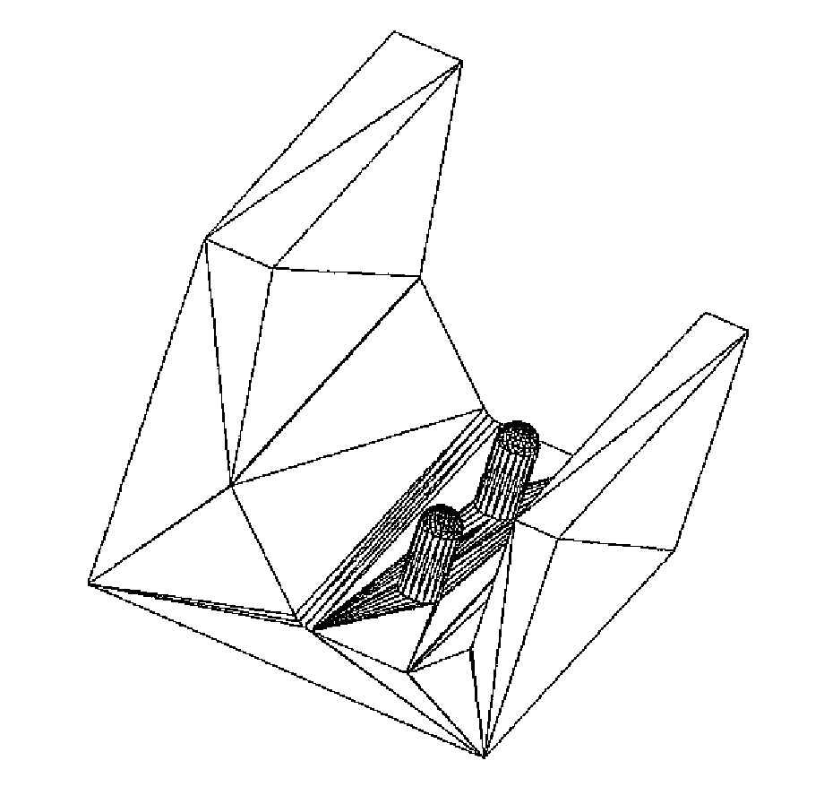
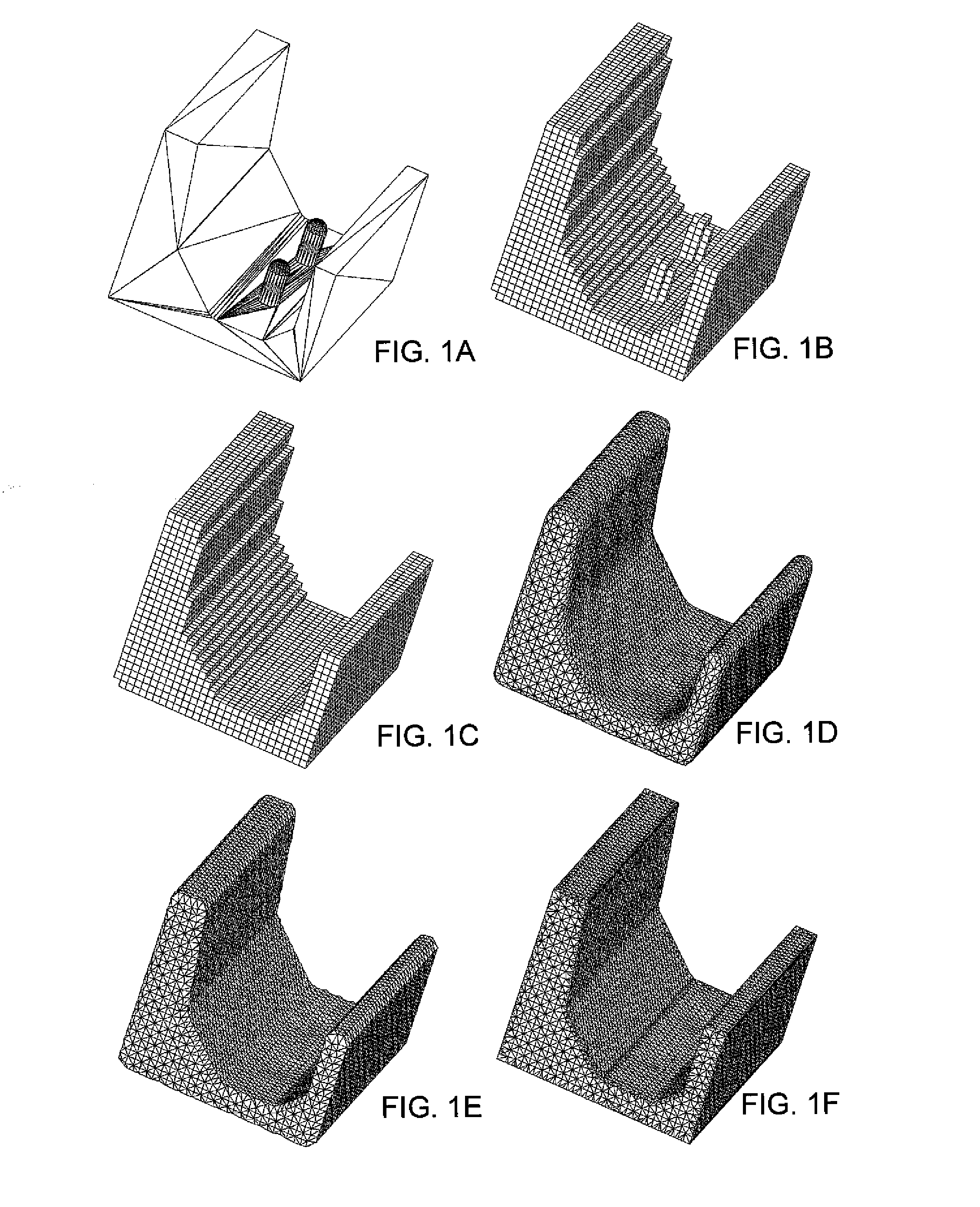
[0056]An overview of a method that comprises one an embodiment of the invention is discussed first with reference to FIGS. 1A to 1F. FIG. 1A shows the master boundary representation of a virtual three-dimensional object, also referred to below as the original CAD model. This can be obtained from or created by any conventional CAD software package, and the representation is rendered on a display or other output associated with a computer which includes at least one processor configured by code executing therein to provide the functionality and transformations of data maintained in a non-transitory memory device, as discussed in this specification.

[0057]The code utilized by one or more embodiments of the present invention comprise instructions that control the processor of the computer to execute methods, such as detailed in FIGS. 7 and 8 below. The instructions can comprise a program, a single module, or a plurality of modules that operate in cooperation with one another. More genera...


PUM

PropertyMeasurementUnit
signed distanceaaaaaaaaaa
volumeaaaaaaaaaa
physical modelaaaaaaaaaa

Abstract

A computer-implemented image processing technique for selectively recovering the features of an original CAD model after the original CAD model has been converted to a digitized image and a new CAD model generated from the digitized image. The original boundary representation provides a template to transform the representation through processing under governance of a programmed processor so as to recover accuracy and reintroduce feature edges and feature corners as well as other detailed features to the CAD model obtained from the digitized image, e.g., to enable detailed features to be retained that would otherwise have been lost due to the lossy conversion into image space. The method operates to better ensure that reconstructed boundary vertices lie on original CAD model surfaces and feature edges and corners are recovered.

Description

[0001]The present application claims the benefit of priority under 35 U.S.C. §119 of GB 1311293.3, filed 25 Jun. 2013, which is hereby incorporated by reference in its entirety.FIELD OF THE INVENTION[0002]The invention relates to computer-assisted methods for the preparation of images for further processing. For example, the prepared images can be for use in subsequent analysis techniques, such as finite element analysis or computational fluid dynamic (CFD) analysis, or as a more robust image for computer-assisted design (CAD) manipulation. In another example, an image can be prepared for use in a manufacturing process, such as three-dimensional printing, CNC machining, injection moulding or the like.BACKGROUND TO THE INVENTION[0003]CAD models are often constructed in a way that makes certain types of subsequent processing, such as the creation of real physical models (e.g., by three-dimensional printing or rapid prototyping) or volume and surface meshes, not possible without manual...

Claims


Application Information

Patent Timeline
Patent Type & Authority Applications(United States)
IPC IPC(8): G06T17/10B23Q15/007G05B19/416B29C67/00
CPCG06T17/10B29C67/0088G05B2219/49065G05B19/4163B23Q15/007B33Y50/00B29C64/112G06F30/00Y02P90/02G06T17/20G06T17/30G06T15/04G06T19/20
Inventor YOUNG, PHILIPPE GEORGESRAYMONT, DAVIDPARANJAPE, SUMIT
Owner SYNOPSYS INC
Why Eureka
Try Eureka