

Pump assembly
a technology for assembling parts and cylinders, applied in mechanical equipment, sliding contact bearings, liquid fuel engines, etc., can solve the problem that the bearing holder is not designed as a solid material, and achieve the effect of convenient formation
- Summary
- Abstract
- Description
- Claims
- Application Information
AI Technical Summary
Benefits of technology
Problems solved by technology
Method used
Image

Examples
Embodiment Construction
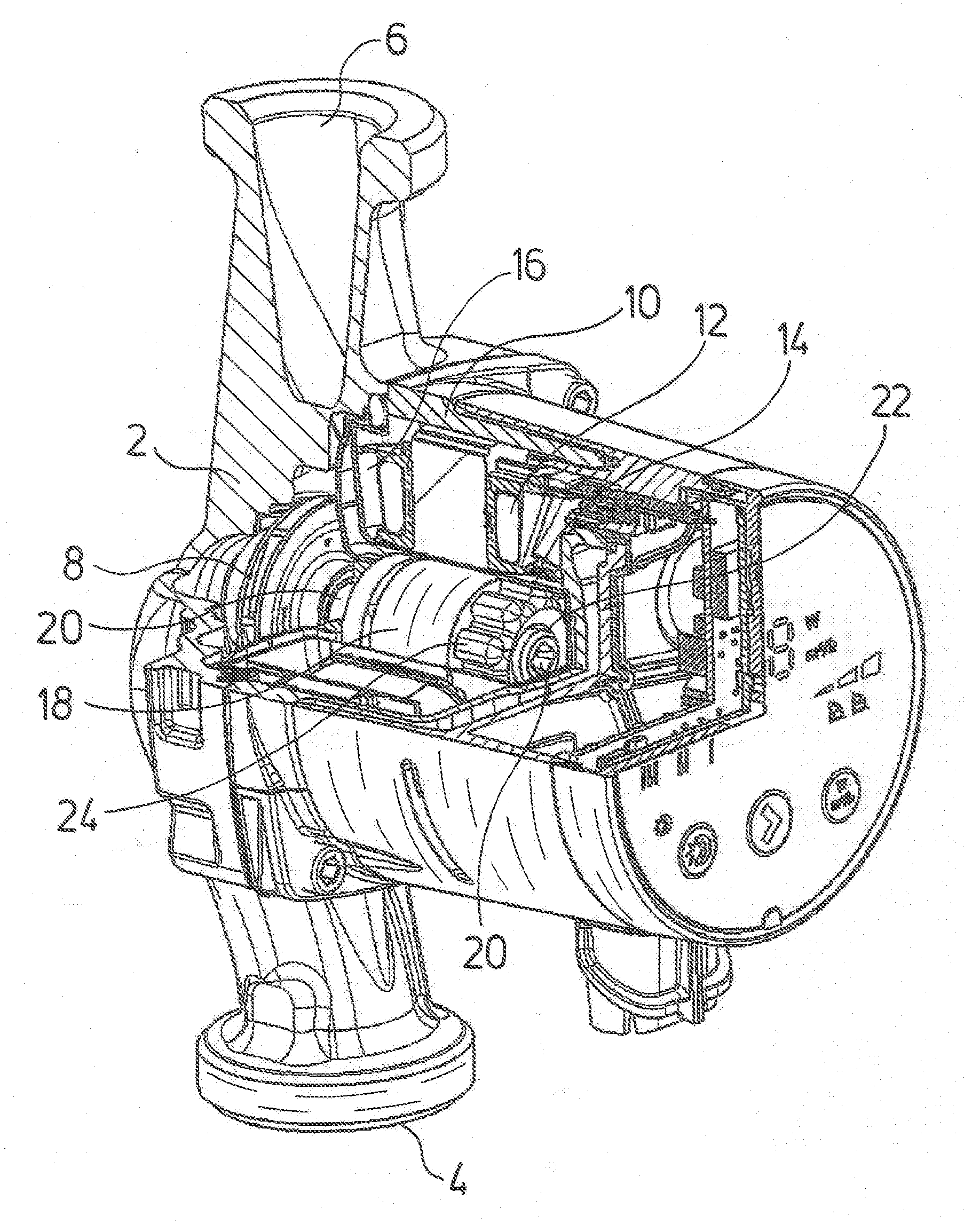
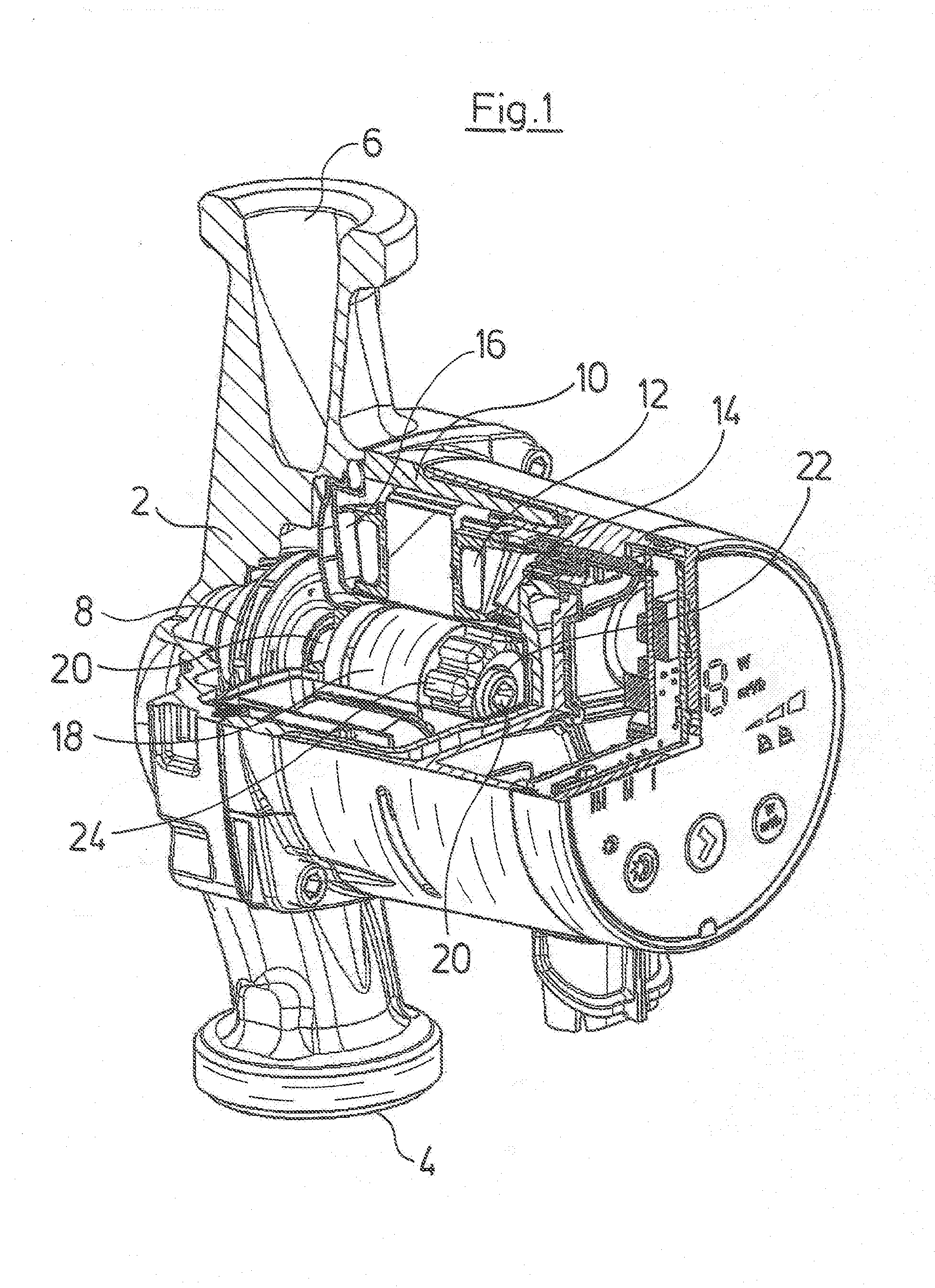
[0029]The pump assembly according to FIG. 1 is a heating circulation pump assembly which in the known manner comprises a pump housing 2 with a suction connection 4 and a pressure connection 6. An impeller 8 is arranged in the pump housing 2. A stator housing 10 with a stator 12 of an electrical drive motor which is arranged thereon, is applied onto the pump housing 2. The electric drive motor is designed as a canned motor. This means that a can pot 14 is arranged in the inside of the stator 12, said can pot via a radially outward projecting collar 16 sealing the region of the stator housing 10, in which the stator 12 is arranged, to the interior of the pump housing 2, in which the fluid to be delivered is located. A rotor 18 is arranged in the inside of the can pot 14 and rotatingly drives the impeller 8 via the motor shaft 20. The motor shaft 20 at its axial end, which is away from the impeller 8, is mounted in a radial bearing 22. The radial bearing 22 for its part is fixed in a b...
PUM
 Abstract
Description
Claims
Application Information