Motion analysis device

a technology of motion analysis and motion, which is applied in the direction of instruments, gymnastics, teaching apparatus, etc., can solve the problems of difficult installation of the system in an outdoor location, lack of convenience, and difficulty in establishing the orientation of the face at impact substantially the same as at address, so as to facilitate the rotation of the shaft portion and facilitate the motion of the wris

Inactive Publication Date: 2014-12-25
SEIKO EPSON CORP
View PDF8 Cites 60 Cited by
  • Summary
  • Abstract
  • Description
  • Claims
  • Application Information

AI Technical Summary

Benefits of technology

[0007]An advantage of some aspects of the invention is to provide a motion analysis device capable of easily presenting the rotation of the shaft portion of the sporting equipment as a measure in the motion analysis, and a motion analysis device capable of easily presenting the motion of the wrist in connection with the swing action in a visual manner.

Problems solved by technology

However, in reality, it is very difficult to establish the orientation of the face at impact substantially the same as at address as expected.
By using an optical motion capture system equipped with a plurality of cameras, it is possible to shoot the face angle of the hitting area of the golf club at address and at impact to identify the orientation of the face angle from the images, which lacks convenience on the grounds that the system is large in scale, and it is difficult to install the system in an outdoor location.
As known to the art, if it is attempted to adjust the face of the club head by rolling the wrist immediately before the impact, the adjustment is delayed, and the face at impact is rather disturbed by rolling the wrist, which negatively affects the swing.
The motion of the wrist in the golf swing is difficult to observe by the optical motion capture using the cameras and so on, and it is unachievable to trace such a precise movement as the delicate roll of the wrist.
In the case of making a precise tracing, it is necessary to prepare a lot of high-precision cameras, which makes the measurement system large in scale.
Further, the optical motion capture using the cameras and so on can only be used in the indoor measurement, but cannot be used in the field of the typical outdoor practice.
Since the shaft of the sporting equipment has a rod-like shape, there is a problem that even if the rotation around the axis of the shaft is displayed, it is difficult for the teat subject to figure out the amount of the rotation.

Method used


Image

  • Motion analysis device
  • Motion analysis device
  • Motion analysis device

Examples


first embodiment

3. Configuration of Arithmetic Processing Circuit of First Embodiment

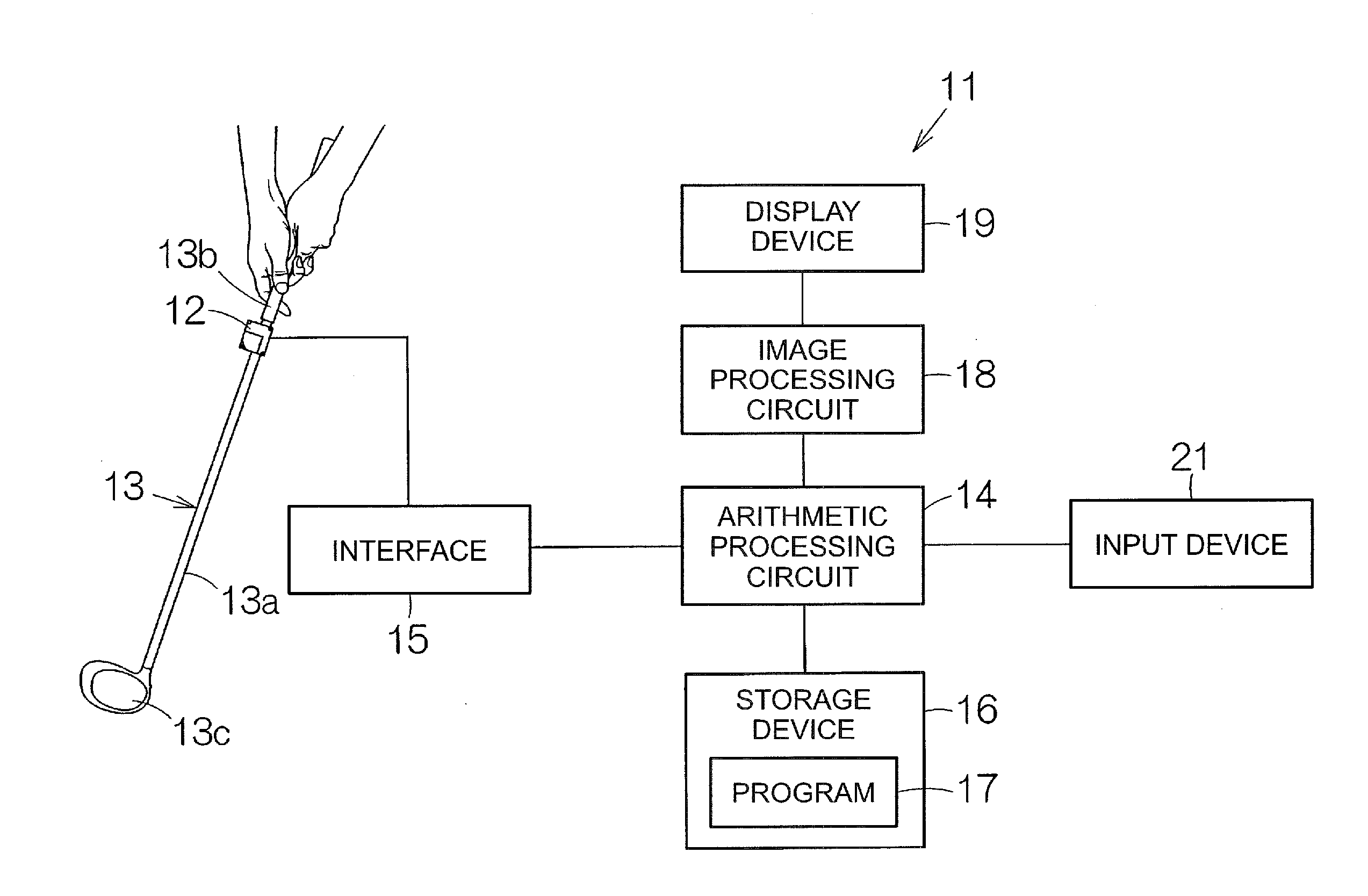
[0049]FIG. 3 schematically shows the configuration of the arithmetic processing circuit 14 according to the embodiment. The arithmetic processing circuit 14 is provided with a first detection section 31 and a second detection section 32. The first detection section 31 and the second detection section 32 are each connected to the inertial sensor 12. The first detection section 31 and the second detection section 32 are each supplied with an output from the inertial sensor 12.

[0050]The first detection section 31 detects an initial position of the grip 13b around an axis (coaxial with the shaft 13a) of the grip 13b based on the output of the inertial sensor 12. When performing the detection, the first detection section 31 obtains the angular velocity at address around a detection axis (here the y axis) parallel to the shaft 13a using the inertial sensor 12. The first detection section 31 sets the angular velocity thus...

second embodiment

[0079]Hereinafter, a second embodiment of the invention will be explained with reference to FIGS. 8, 9, and 10. It should be noted that in the following explanation, “1. Configuration of Golf Swing Analysis Device” and “2. Motion Analysis Model,” which have substantially the same configurations as those of the first embodiment described above, will be denoted with the same reference symbols, and the explanation thereof will be omitted.

3. Configuration of Arithmetic Processing Circuit of Second Embodiment

[0080]FIG. 8 schematically shows the configuration of the arithmetic processing circuit 14 according to the embodiment. The arithmetic processing circuit 14 is provided with a swing locus calculation section 51 as a first calculation section and a rotational angle calculation section 52 as a second calculation section. The swing locus calculation section 51 is connected to the inertial sensor 12. The swing locus calculation section 51 is supplied with an output signal from the inerti...


PUM


Abstract

In a motion analysis device, a first detection section detects a first state of a shaft portion of sporting equipment using an output of an inertial sensor. The first state corresponds to, for example, a resting state. A second detection section detects a second state of the shaft portion of the sporting equipment using the output of the inertial sensor. The second state corresponds to, for example, an impact. The second detection section detects a relative rotational angle of the shaft portion having varied around an axis of the shaft portion from the first state.

Description

BACKGROUND[0001]1. Technical Field[0002]The present invention relates to a motion analysis device.[0003]2. Related Art[0004]A motion analysis device is used for an analysis of a motion such as a swing action. When making a swing, sporting equipment is swung. When swinging the sporting equipment, a grip of the sporting equipment is held by hand. When the sporting equipment is swung, the posture of the sporting equipment varies in accordance with the time axis. An inertial sensor is mounted on the sporting equipment. The swing action is visually reproduced based on an output of the inertial sensor. As a specific example of such a motion analysis device, there can be cited, for example, a golf swing analysis device as disclosed in JP-A-2008-73210.[0005]For example, golf swing starts with address, and then reaches the follow-through and then finish via a take-back action, a halfway back position, downswing from a top position, and an impact. At the beginning of the golf swing, at addres...

Claims


Application Information

Patent Timeline
Patent Type & Authority Applications(United States)
IPC IPC(8): A63B24/00G01C19/00G01P15/18G01P15/02A63B69/36A63B71/06
CPCA63B24/0006A63B69/36A63B71/0619G01P15/18A63B2220/836G01C19/00A63B2071/0647A63B2220/51A63B2220/833G01P15/02G09B19/003A63B69/3632A63B60/46A63B15/00A63B2220/30
Inventor SATO, MASAFUMISHIBUYA, KAZUHIROKODAIRA, KENYANOMURA, KAZUO
Owner SEIKO EPSON CORP
Why Eureka
Try Eureka