Solar mounting system having automatic grounding and associated methods

a solar panel and automatic grounding technology, applied in the direction of heat collector mounting/support, curtain suspension devices, lighting and heating apparatus, etc., can solve the problems of difficult electrical bonding and/or grounding of panel frames in solar mounting systems, significant additional hours of labor needed during installation for any additional steps, and achieve the effect of reducing the time to production

Active Publication Date: 2015-01-01
RBI SOLAR
View PDF5 Cites 42 Cited by
  • Summary
  • Abstract
  • Description
  • Claims
  • Application Information

AI Technical Summary

Benefits of technology

[0017]According to another embodiment, a method of installing a solar mounting system includes establishing a support structure on a base surface. The support structure includes a plurality of support members and at least one elongated support rail supported by at least one of the plurality of support members and having a grounding structure defining a raised edge formed from material of the at least one elongated support rail and projecting outwardly from the at least one elongated support rail. The method also includes positioning at least one solar panel adjacent to the at least one elongated support rail and securing the panel frame with the at least one elongated support rail. The solar panel is grounded by providing direct electrical contact between the raised edge on the elongated support rail and conductive material of the panel frame as the panel frame is secured with the elongated support rail. As a result, the grounding of the solar panel automatically occurs without requiring additional components or assembly steps that increase the cost of the assembly. More specifically, the raised edge may cut through a protective coating on the panel frame (when such a protective coating is present) as the solar panel is secured into position on the solar mounting system.
[0019]The counterform punching of the fastener aperture may include a series of operations. For example, the counterform punching includes positioning the sheet of material within a counterform press between a hollow die button and an upper forming die including a punch, and then driving the punch and the upper forming die into the sheet of material to cause the punching and deformation required to form the fastener aperture. More particularly, a portion of the sheet of material may be removed in order to define a fastener aperture or a clamp aperture in the sheet of material, and then another portion of the sheet of material may be deformed to produce the raised edge proximate to or spaced from the fastener aperture. This process adds minimal time to the production of the elongated support rail and avoids the need for additional components and installation steps to be used while grounding a solar panel in the resulting solar mounting system.

Problems solved by technology

Each separate step that must be performed to reliably connect and mount a solar panel onto the support structure must be repeated hundreds or thousands of times in this context, which results in significant additional hours of labor needed during installation for any additional steps that become necessary when mounting each solar panel.
However, the grounding of panel frames in solar mounting systems is made difficult by other design considerations necessary for solar mounting systems, such as the need to protect the conductive portion of the panel frames from harsh environmental conditions that may lead to corrosion and deterioration of the panel frames.
But this protective coating makes it difficult to readily form an electrical bonding and / or grounding connection with the conductive portion of the panel frames, which is required when grounding solar panels.
Both of these grounding lugs require multiple connections between the parts described above to reliably form the electrical bonding path between the copper wire and the panel frame, and the installation of these grounding lugs is time-consuming and complex.
The additional wiring of the copper wire to each of the grounding lugs also adds additional time and expense that multiplies exponentially when producing a large solar mounting system.
The accurate alignment and insertion of these star washers for each solar panel increases the complexity and cost of manufacturing larger solar mounting systems.
For example, if the star washers are not formed strong enough for the teeth to resist the compressive forces on the solar panel and the supporting structure, the teeth may bend in some washers back to a planar state with the washer body, which causes a lack of electrical contact between the panel frame and the support structure.
However, each of these alternatives to star washers still requires additional installation work and cost to add these separate grounding components during the construction of a solar mounting system.
Even if several of these alternative grounding components function better or are installed more rapidly than a grounding lug or a star washer, there are still additional costs associated with providing these grounding components for each solar panel and then installing these grounding components.
For example, a star washer that may cost a few cents or a modified bonding washer that may cost a bit more are minimal in costs by themselves, but these parts are required for each connection made to the solar panels, and this incremental cost aggregates into a significant added expense for larger assemblies.

Method used


Image

  • Solar mounting system having automatic grounding and associated methods
  • Solar mounting system having automatic grounding and associated methods
  • Solar mounting system having automatic grounding and associated methods

Examples


Embodiment Construction

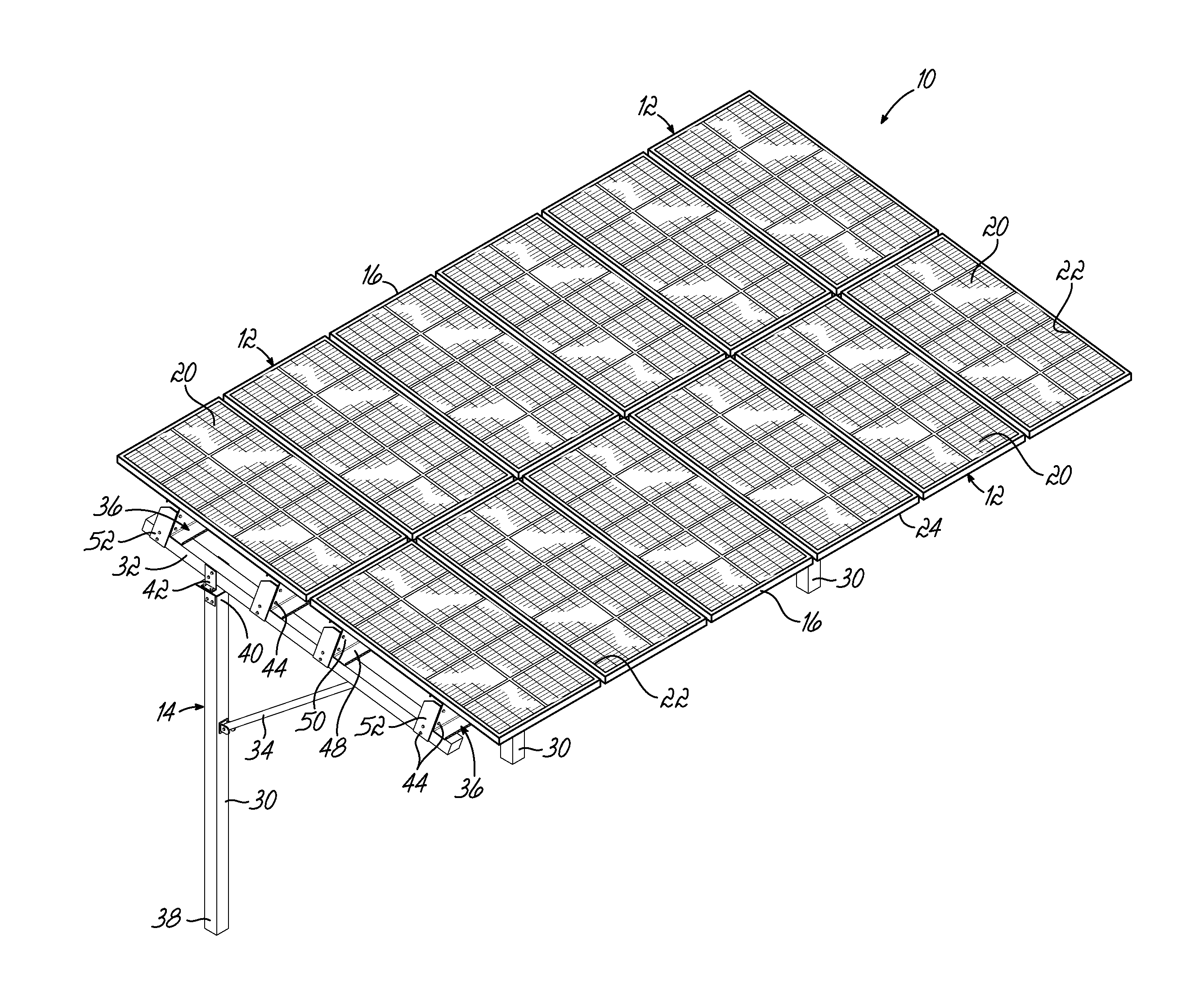
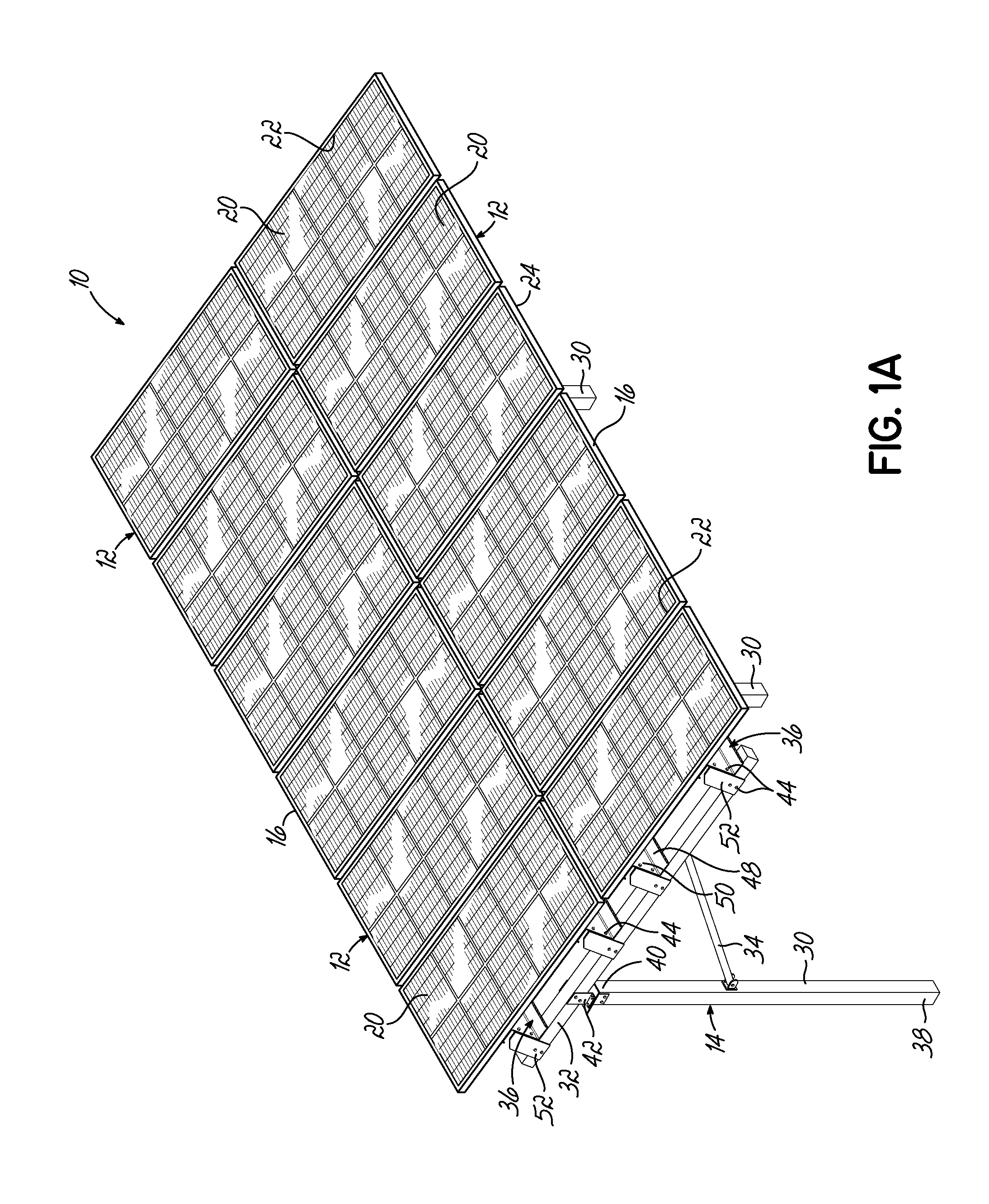
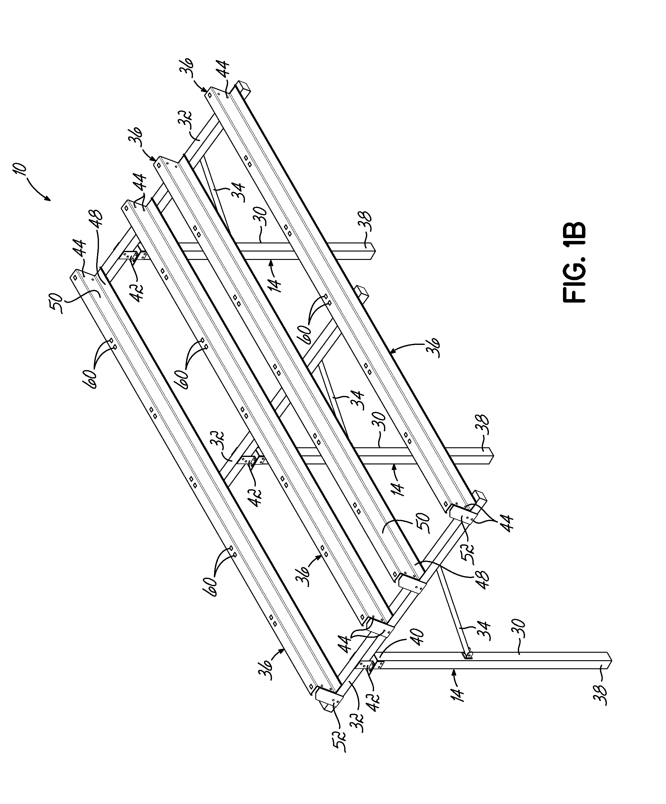
[0037]With reference to FIGS. 1A through 5, an exemplary embodiment of a solar mounting system 10 that enables mounting and automatic grounding of a plurality of solar panels 12 is shown. The solar mounting system 10 shown in FIG. 1A includes twelve solar panels 12 arranged in a 6-by-2 grid (e.g., in a portrait orientation) on top of a support structure 14 that is tailored in size to the number of solar panels 12 to be supported. It will be understood that the particular number and arrangement of the solar panels 12 can be modified in other embodiments, such as in larger assemblies (e.g., up to hundreds or thousands of solar panels 12) used for commercial or utility power generation, without departing from the scope of the invention. For example, FIG. 1C described in further detail below illustrates an alternative embodiment of the solar mounting system 10 in which the solar panels 12 are supported in a landscape orientation. The support structure 14 of the solar mounting system 10 ...


PUM

PropertyMeasurementUnit
thickness TPaaaaaaaaaa
sizeaaaaaaaaaa

Abstract

A solar mounting system includes at least one solar panel with a panel frame and a support structure including at least one elongated support rail configured to support the panel frame of the at least one solar panel. The elongated support rail includes a grounding structure with a raised edge formed from material of the at least one elongated support rail. The raised edge is configured to cut through a protective coating surrounding a conductive material forming the panel frame, thereby grounding the solar panel by providing direct electrical contact between the panel frame and the at least one elongated support rail. This automatic grounding does not require additional grounding equipment or elements to be added to the solar mounting system.

Description

FIELD OF THE INVENTION[0001]The present invention relates generally to a solar mounting system and, more particularly, to grounding of solar panels that are mounted using the solar mounting system.BACKGROUND[0002]Solar mounting systems, designed for supporting varying numbers of solar panels with photovoltaic cells, are being installed as an alternative source of energy in many different settings, including smaller residential assemblies and larger commercial or utility assemblies. Especially in the context of larger solar mounting systems containing hundreds or thousands of solar panels at a single installation site, it is desirable to simplify the process and cost of installing the solar panels onto the support structures that maintain the solar panels raised above a base surface such as a roof or ground. Each separate step that must be performed to reliably connect and mount a solar panel onto the support structure must be repeated hundreds or thousands of times in this context, ...

Claims


Application Information

Patent Timeline
Patent Type & Authority Applications(United States)
IPC IPC(8): H01L31/042F16M13/02H01L31/18
CPCH01L31/0422H02S20/00H01L31/18F16M13/02F24J2/52H02S20/10H02S20/20H02S20/23Y10T29/49002F24S25/12F24S25/35F24S25/632F24S25/636F24S25/70Y02B10/10Y02E10/47Y02E10/50
Inventor REILLY, RICHARD T.VIETAS, WILLIAM L.
Owner RBI SOLAR
Why Eureka
Try Eureka