Touch sensing apparatus and method of driving the same

a sensing apparatus and touch technology, applied in the field of touch sensing apparatus, can solve the problems of reducing the sensing capability the parasitic capacitance deviation between the outer readout channel and the outer portion, and the increase of the outermost readout channel, so as to reduce the parasitic capacitance and reduce the noise. , the effect of reducing the parasitic capacitan

Active Publication Date: 2015-01-01
LG DISPLAY CO LTD
View PDF9 Cites 27 Cited by
  • Summary
  • Abstract
  • Description
  • Claims
  • Application Information

AI Technical Summary

Benefits of technology

[0022]The touch controller is configured to provide a signal through the dummy routing line to at least reduce the parasitic capacitance deviation between the at least one outermost readout channel and other readout channels and / or to at least reduce the parasitic capacitance between the at least one outermost readout channel and the ground routing line.
[0023]In another aspect of the present invention, a method of driving a touch sensing apparatus includes supplying a signal through the dummy routing line to at least reduce a noise caused by the at least one outermost readout channel. The signal has the same phase as a readout signal of the outermost readout channel.

Problems solved by technology

However, as a ground line formed on a bezel area of a touch sensor is located close to an outermost readout channel adjacent to the ground line, parasitic capacitance formed between a ground routing line and an outermost readout channel is increased, thereby increasing parasitic capacitance deviation between outer readout channels positioned on an outer portion.
Problems arise in that the noise component of the outermost readout channel is increased in proportion to this parasitic capacitance deviation, thereby reducing the sensing capability of the outermost readout channel.
In this case, problems arise in that parasitic capacitance variation and noise component due thereto is reduced, whereas the width of an outer bezel area is increased.

Method used


Image

  • Touch sensing apparatus and method of driving the same
  • Touch sensing apparatus and method of driving the same
  • Touch sensing apparatus and method of driving the same

Examples


Embodiment Construction

[0032]Reference will now be made in detail to the preferred embodiments of the present invention, examples of which are illustrated in the accompanying drawings.

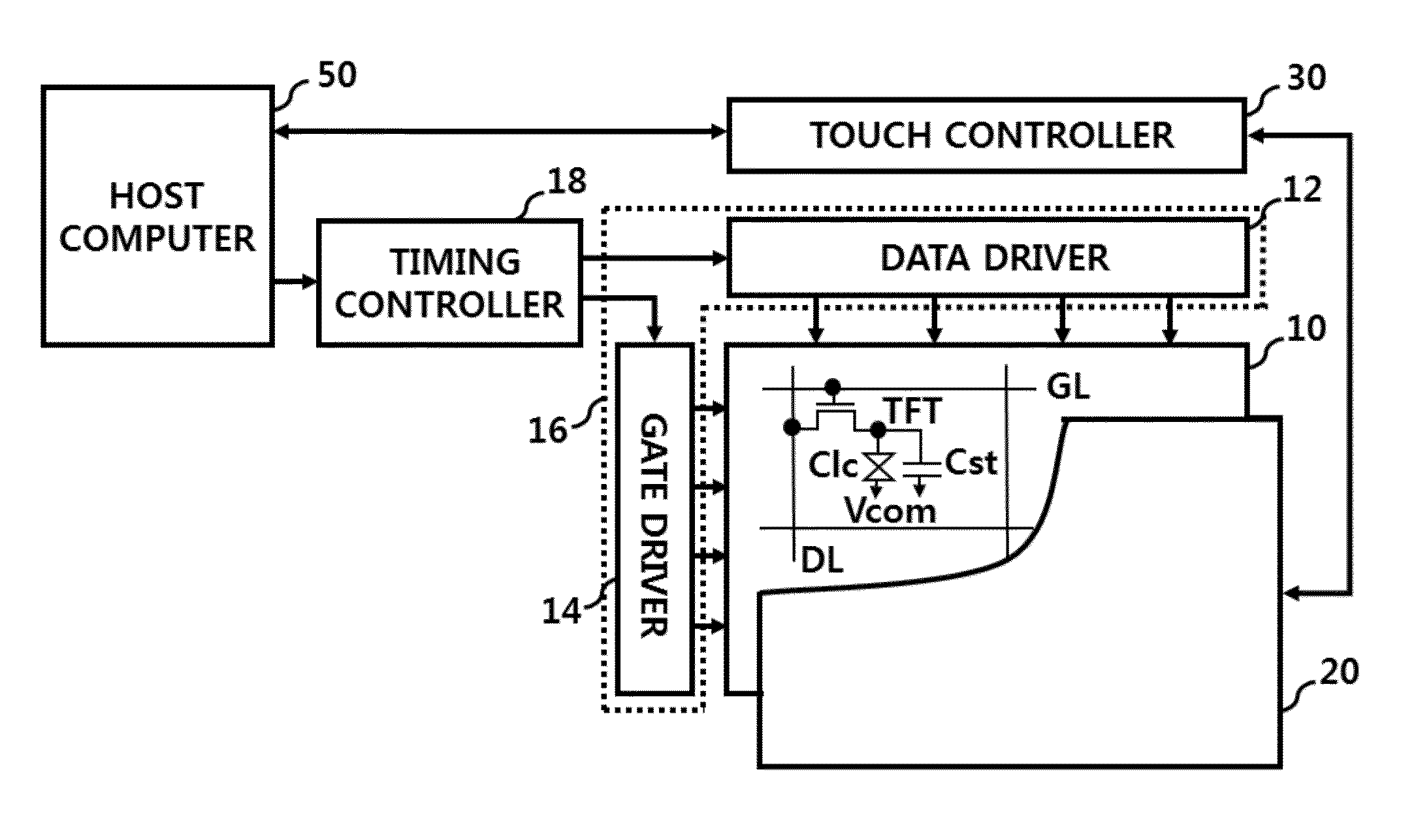
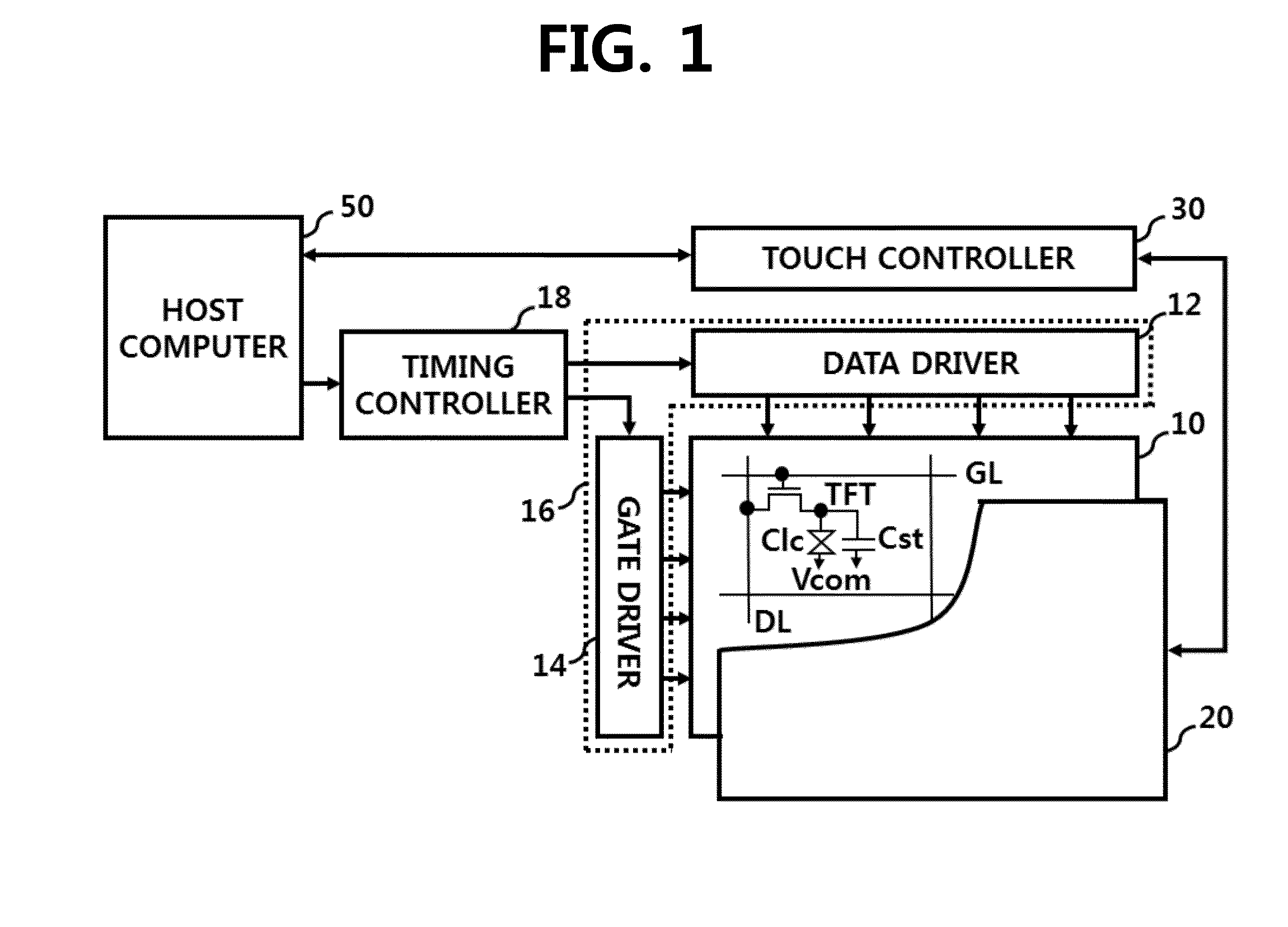
[0033]FIG. 1 is a block diagram illustrating a structure of a display apparatus including a touch sensing apparatus according to an embodiment of the present invention.

[0034]The display apparatus including the touch sensing apparatus illustrated in FIG. 1 includes a display panel 10, a panel driver 16 including a data driver 12 and a gate driver 14 for displaying the display panel 10, a timing controller 18 for controlling the panel driver 16, a touch sensor 20 on the display panel 10, and a touch controller 30 for driving the touch sensor 20. The timing controller 18 and the touch controller 30 are connected to a host computer 50. All components of the display apparatus are operatively coupled and configured.

[0035]The timing controller 18 and the data driver 12 may be integrated as respective integrated circuits (ICs) or th...


PUM


Abstract

A touch sensing apparatus includes a touch sensor and a touch controller for sensing whether touch is present from a readout signal of the touch sensor as well as driving the touch sensor, wherein the touch sensor includes a plurality of scan channels including a plurality of first sensing electrodes arranged in a first direction in a sensing area, a plurality of readout channels including a plurality of second sensing electrodes arranged in a second direction that crosses the first direction in the sensing area, a ground routing line formed to surround the sensing area in a bezel area surrounding the sensing area, a dummy routing line formed between the ground routing line and an outermost readout channel among the plural readout channels in the bezel region, wherein a signal with the same phase as the outermost readout channel is supplied to the dummy routing line.

Description

[0001]This application claims the benefit of Korean Patent Application No. 10-2013-0073705, filed on Jun. 26, 2013, which is hereby incorporated by reference as if fully set forth herein.BACKGROUND OF THE INVENTION[0002]1. Field of the Invention[0003]The present invention relates to a touch sensing apparatus, and more particularly, to a touch sensing apparatus and a method of driving the same, for reducing the width of a bezel area while reducing noise of an outermost readout channel.[0004]2. Discussion of the Related Art[0005]Today, a touch sensor that can input information via touch on screens of various display apparatuses has been widely used as an information input apparatus of a computer system. The touch sensor moves or selects displayed information by simply touching a screen via a user finger or a stylus and thus can be easily used regardless of age or sex.[0006]A touch sensing apparatus detects a touch and a touch location on a touch sensor of a display apparatus and outpu...

Claims


Application Information

Patent Timeline
Patent Type & Authority Applications(United States)
IPC IPC(8): G06F3/044
CPCG06F3/044G06F3/0418G06F3/045G06F2203/04107G06F3/04184G06F3/0446
Inventor LEE, BYOUNG-GWANSHIN, MYUNG-HOLIM, DONG-KYUNKIM, YOUNG-GYU
Owner LG DISPLAY CO LTD
Why Eureka
Try Eureka