
Vehicle headlight

a headlight and vehicle technology, applied in the field of vehicles, can solve the problems of incongruity in the contrast, driver's sense of incongruity, driver's perception of incongruity, etc., and achieve the effect of reducing the contras

Active Publication Date: 2015-01-01
SUBARU CORP
View PDF6 Cites 8 Cited by
  • Summary
  • Abstract
  • Description
  • Claims
  • Application Information

AI Technical Summary

Benefits of technology

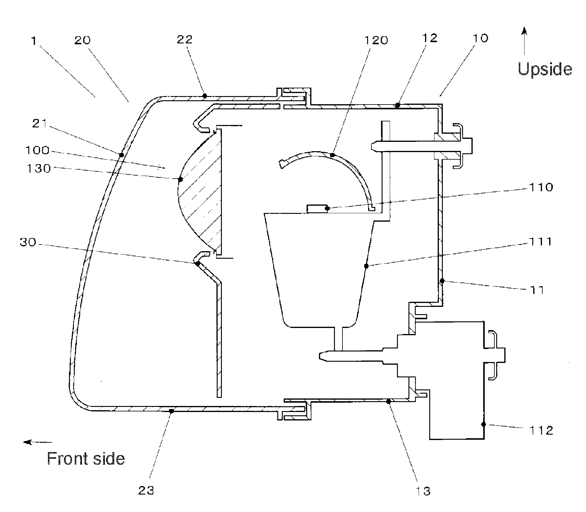
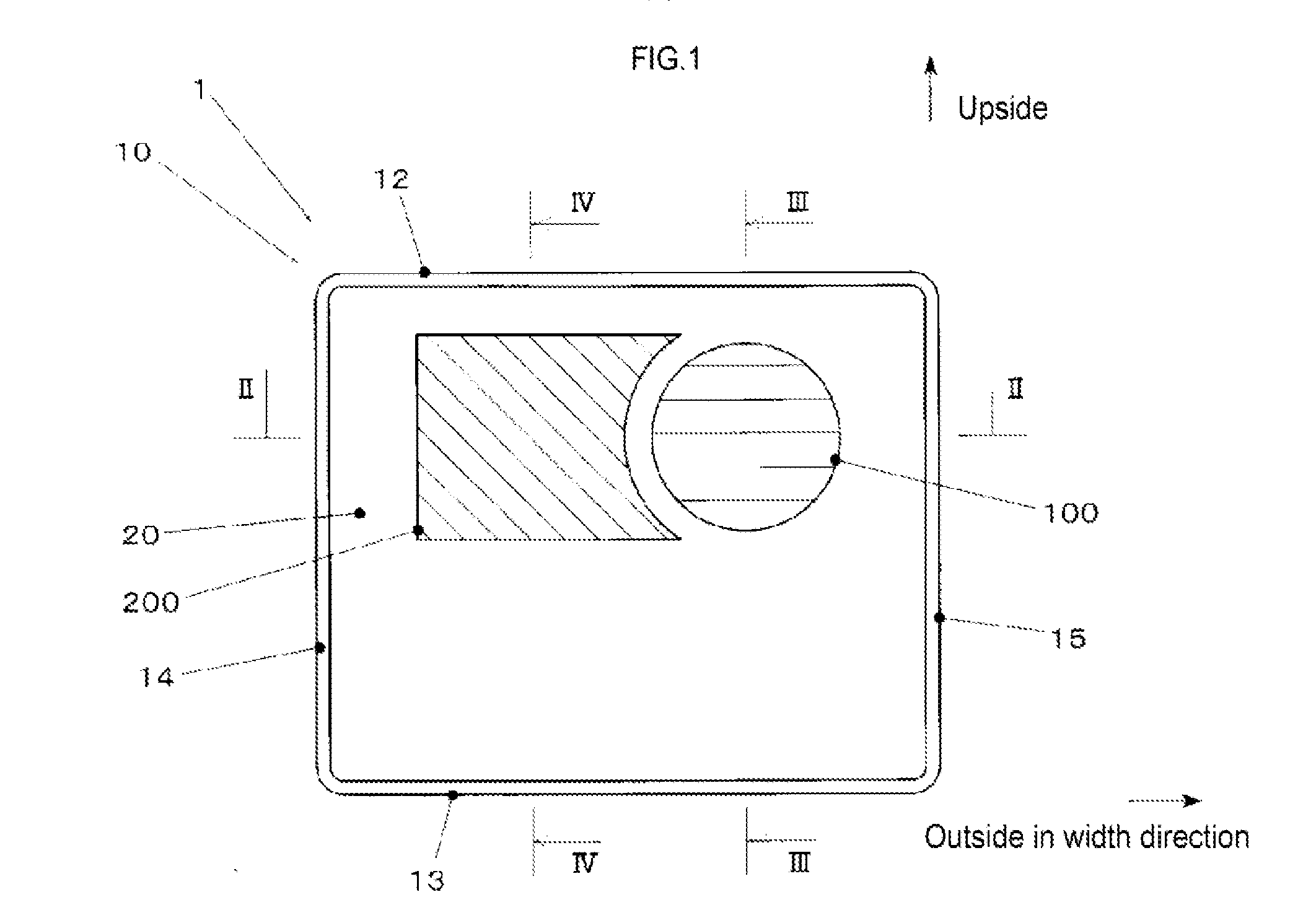
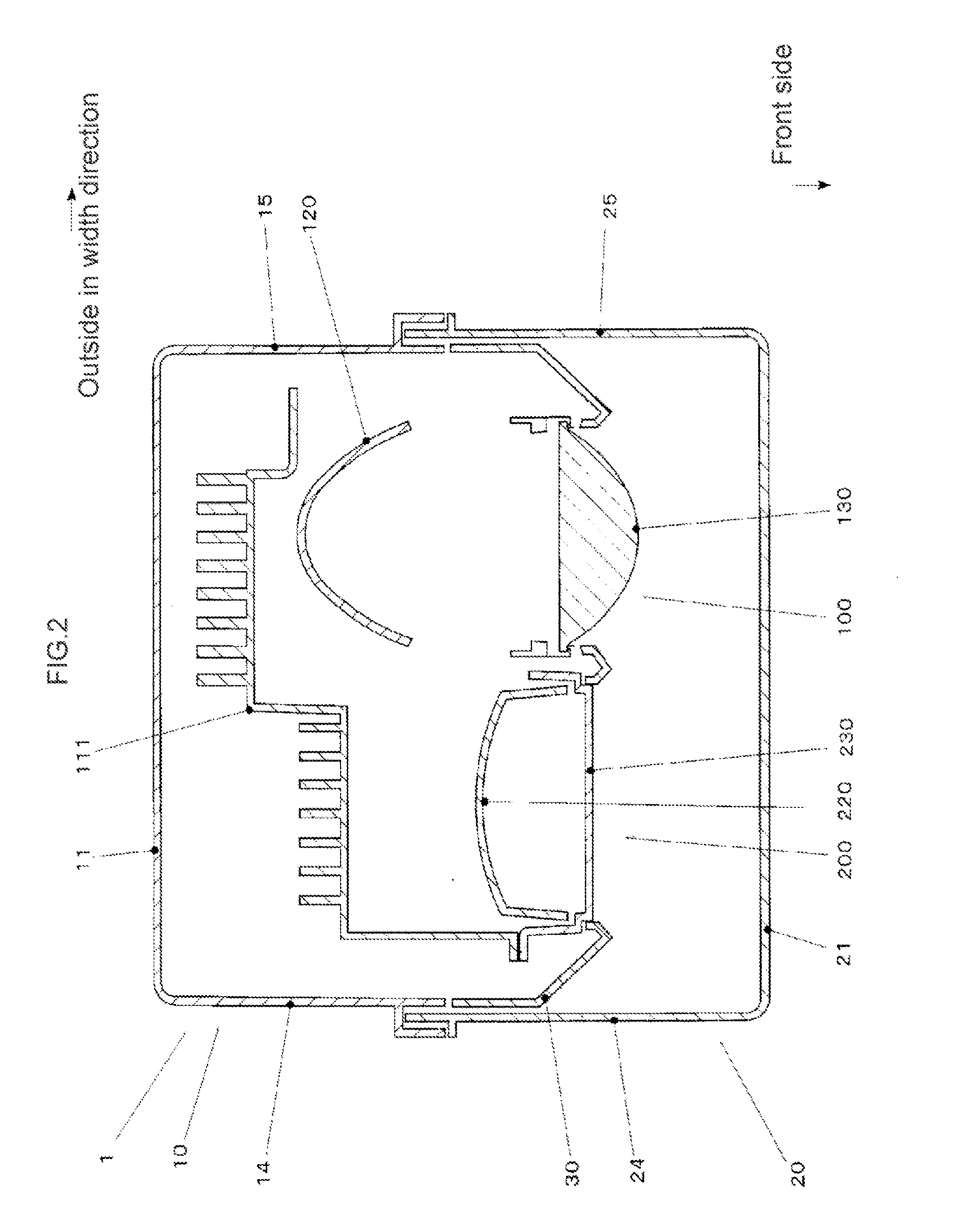
The invention aims to create a vehicle headlight that minimizes the difference in brightness between the top and bottom parts of the headlight's cut-off line, which helps prevent the driver from feeling uneasy or uncomfortable. It also aims to reduce the glare that drivers may feel from other vehicles, making the road safer for everyone.

Problems solved by technology

However, since a clear cutoff line is formed due to the structure, a driver may feel a sense of incongruity in the contrast above and below the cutoff line.
However, in the case where the cutoff line on the left and right sides of the elbow point is illuminated with the reflector unit as with the technique disclosed in JP-A No. 2001-195910, light is distributed additionally to a region that is already illuminated uniformly with a main light distribution pattern on the non-oncoming lane side (vehicle side) of the elbow point, and a resulting non-uniformity of the light distribution pattern on a road surface may cause a driver to feel a sense of incongruity.
Therefore, a driver of an oncoming vehicle or a preceding vehicle may be dazzled by the glare.

Method used


Image

  • Vehicle headlight
  • Vehicle headlight
  • Vehicle headlight

Examples


modified example

[0134]The present invention is not limited to the example described above. Various modifications and changes are possible and within the technical scope of the present invention.

[0135](1) The shape, structure, material, manufacturing method, and the like of each component forming the headlight are not limited to the configuration of the example described above, and may be changed appropriately.

[0136](2) The headlight in the example is formed of the first unit and the second unit. However, other units may be added.

[0137](3) In the example, the light distribution pattern of the second unit is provided only in a region adjacent to a part of the cutoff line of the first unit. However, the light distribution pattern of the second unit may include other regions.

[0138]For instance, the light distribution pattern of the second unit may include a region corresponding to a shoulder ahead of the vehicle for early detection of a pedestrian.

[0139]Also, the light distribution pattern of the secon...


PUM


Abstract

A vehicle headlight includes: a first illuminator including a projector unit that has a projection optical system and illuminates a predetermined region ahead of a vehicle with a first light distribution pattern having a cutoff line at an upper end; and a second illuminator that has a reflector unit including a reflective optical system for illumination with a second light distribution pattern that includes a region on an oncoming lane side of an elbow point of the cutoff line of the first light distribution pattern and that substantially does not include a region on a non-oncoming lane side of the elbow point.

Description

CROSS-REFERENCE TO RELATED APPLICATIONS[0001]The present application claims priority from Japanese Patent Application No. 2013-133684 filed on Jun. 26, 2013, the entire contents of which are hereby incorporated by reference.BACKGROUND[0002]1. Technical Field[0003]The present invention relates to a vehicle headlight provided to a vehicle such as an automobile, and particularly relates to a vehicle headlight that reduces the contrast above and below a cutoff line and prevents a driver of a vehicle from feeling a sense of incongruity and to a vehicle headlight that reduces the contrast above and below a cutoff line and prevents a driver of other vehicles from being dazzled.[0004]2. Related Art[0005]A headlight of a vehicle such as an automobile projects light emitted from a light source such as, for instance, an incandescent light bulb, discharge lamp, and LED with a projection optical system such as a projector and a reflective optical system such as a reflector.[0006]With such a head...

Claims


Application Information

Patent Timeline
Patent Type & Authority Applications(United States)
IPC IPC(8): B60Q1/08F21W107/10
CPCB60Q1/085B60Q1/068B60Q1/076B60Q1/143B60Q2300/21B60Q2300/41B60Q2300/42F21S48/1159F21S48/1258F21S48/1323F21S48/1747F21S48/328F21S41/148F21S41/255F21S41/321F21S41/663F21S45/47
Inventor YAMASAKI, KENTAROU
Owner SUBARU CORP
Learn More