Mixing assemblies including magnetic impellers

a technology of magnetic impellers and mixing assemblies, which is applied in the direction of mechanical equipment, machines/engines, transportation and packaging, etc., can solve the problems of affecting mixing, reducing efficiency, and often not providing the desired mixing efficiency of magnetic impellers

Active Publication Date: 2015-01-01
SAINT GOBAIN PERFORMANCE PLASTICS CORP
View PDF0 Cites 19 Cited by
  • Summary
  • Abstract
  • Description
  • Claims
  • Application Information

AI Technical Summary

Benefits of technology

The present patent relates to magnetic impellers for mixing fluids. The technical effect of this patent is to provide a magnetic impeller that improves mixing efficiency over traditional magnetic stir bars and does not require physical attachment or connection to a vessel. The magnetic impeller has been designed to be used in a wide array of container designs and can be levitated without the need for a separate power source. The patent includes several drawings and illustrations of the magnetic impeller in various configurations.

Problems solved by technology

Such magnetic impellers often do not provide a desired mixing efficiency, particularly in large scale operations.
Moreover, traditional magnetic stir bars have a tendency to “walk” or disengage with the magnetic driving magnet, which can disturb mixing and decrease efficiency.

Method used


Image

  • Mixing assemblies including magnetic impellers
  • Mixing assemblies including magnetic impellers
  • Mixing assemblies including magnetic impellers

Examples


example 1

Levitation

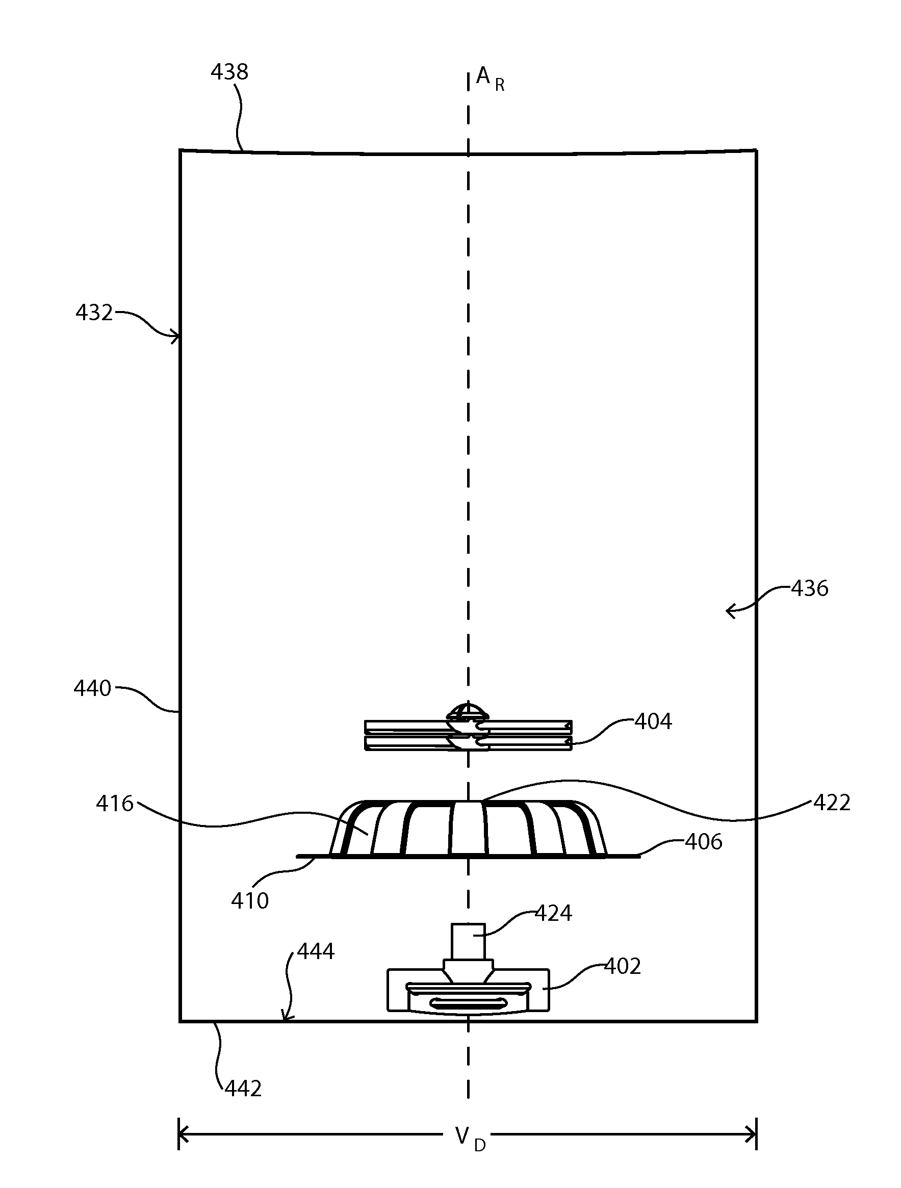
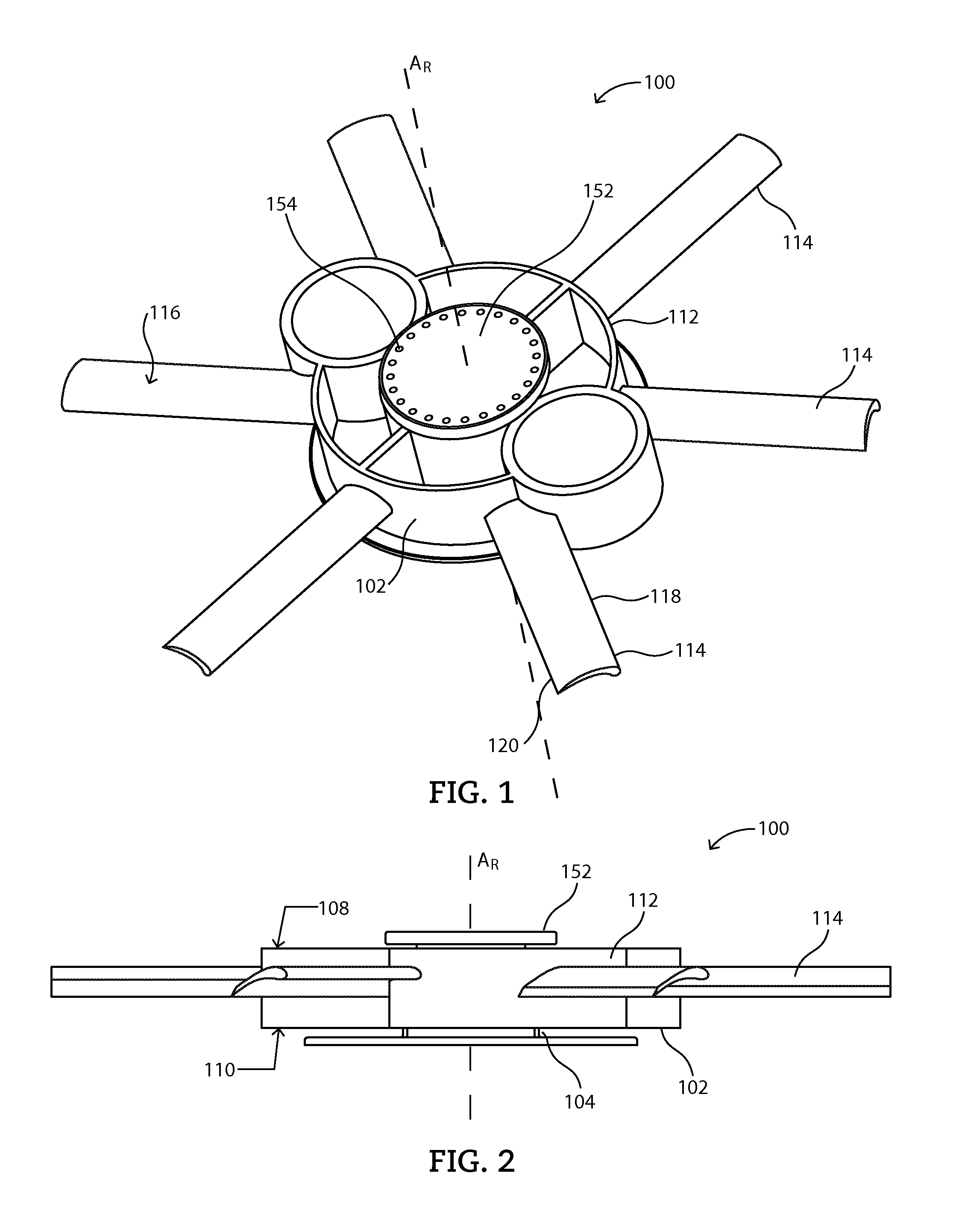
[0245]A magnetic impeller as illustrated in FIG. 1 is fixedly installed within a vessel such that the magnetic impeller will not slide within the vessel during operation. A fluid comprising purified water is introduced into the vessel such that the fluid entirely covers the magnetic impeller. A driving magnet is positioned concomitant with the magnetic member of the magnetic impeller such that a magnetic couple is formed therebetween. A quarter of a cup of course sea salt is then introduced into the fluid within the vessel and the driving magnet is turned on.

[0246]The driving magnet is rotated, causing the magnetic impeller to rotate. The fluid agitating element began to aerodynamically levitate and translate along the column upon a rotation of approximately 65 revolutions per minute.

example 2

Particulate Suspension

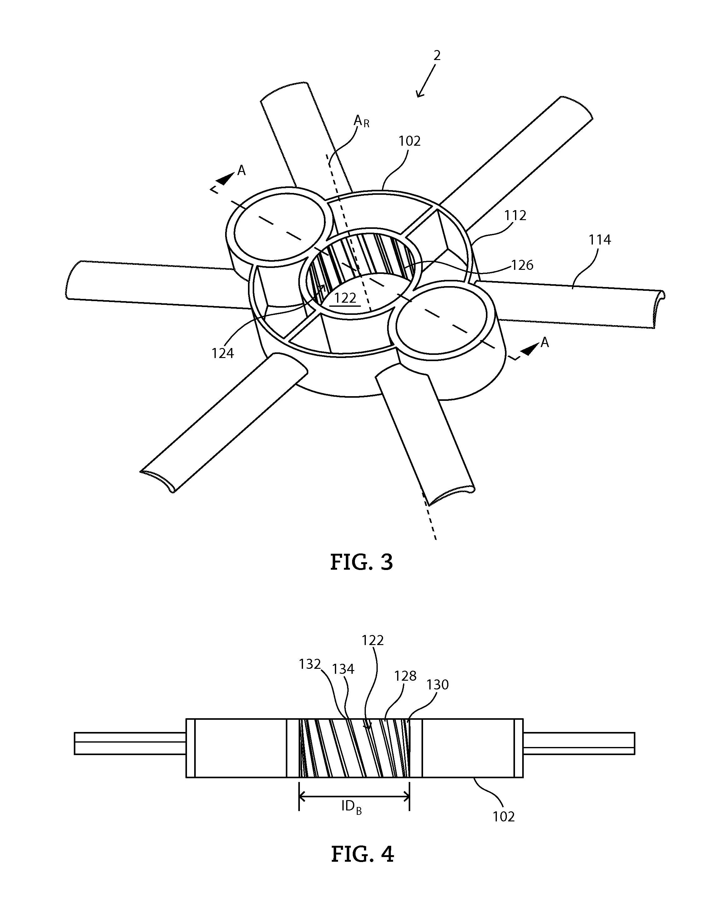
[0247]A magnetic impeller as illustrated in FIG. 1, with the blades as illustrated in FIGS. 19-20 was constructed and tested for its ability to suspend particulate materials at various speeds of rotation. A cylindrical container was filled with 100 L of water. 1000 spherical polymer beads having a specific gravity of 1.2 and an average diameter of 2 cm were added to the water. A magnetic drive was positioned underneath of the vessel and activated. The container was visually observed with a Go Pro® camera and the number of pellets in suspension and out of suspension were counted. A pellet was considered out of suspension if the pellet did not rise above the plane of the blades after a 10 second interval. Similarly, a pellet was considered in suspension if the pellet rises above the plane of the blades within a 10 second interval. The particulate suspension efficiency was then calculated as a percentage of the total number of beads in suspension divided by the to...


PUM


Abstract

The present disclosure relates to improved magnetic mixing assemblies and mixing system. The magnetic mixing assemblies can provide improved mixing action, ease of use, and low friction. The mixing assemblies can be adapted for use with a wide variety of containers including narrower neck containers and flexible containers.

Description

CROSS-REFERENCE TO RELATED APPLICATIONS[0001]This application claims priority under 35 U.S.C. §119(e) to U.S. Provisional Application No. 61 / 841,182 entitled “FLUID MIXING ASSEMBLY,” by Albert A. Werth et al., filed Jun. 28, 2013; claims priority under 35 U.S.C. §119(e) to U.S. Provisional Application No. 61 / 841,189 entitled “DECOUPLED FLUID AGITATOR,” by Albert A. Werth et al., filed Jun. 28, 2013; claims priority under 35 U.S.C. §119(e) to U.S. Provisional Application No. 61 / 874,727 entitled “FREE-STANDING MAGNETIC MIXING ASSEMBLY,” by Albert A. Werth, filed Sep. 6, 2013; claims priority under 35 U.S.C. §119(e) to U.S. Provisional Application No. 61 / 891,477 entitled “BLADED MIXING ASSEMBLY,” by Albert A. Werth, filed Oct. 16, 2013; claims priority under 35 U.S.C. §119(e) to U.S. Provisional Application No. 61 / 915,366 entitled “MIXING ASSEMBLIES HAVING A DECOUPLED FLUID AGITATOR,” by Albert A. Werth et al., filed Dec. 12, 2013; claims priority under 35 U.S.C. §119(e) to U.S. Provis...

Claims


Application Information

Patent Timeline
IPC IPC(8): B01F13/08
CPCB01F13/08B01F13/0863B01F15/0085B01F7/00858B01F2215/0422B01F27/41B01F33/4534B01F35/513
Inventor WERTH, ALBERT A.CAHILL, MICHAEL E.PAGLIARO, JR., ANTHONY P.
Owner SAINT GOBAIN PERFORMANCE PLASTICS CORP
Why Eureka
Try Eureka