Medical needle

Active Publication Date: 2015-01-01
TERUMO KK
View PDF5 Cites 9 Cited by
  • Summary
  • Abstract
  • Description
  • Claims
  • Application Information

AI Technical Summary

Benefits of technology

[0027]In one aspect, the first tube can be narrowed. This can also narrow the wing shaft unit surrounding the first tube. The narrowed wing shaft unit stabilizes the needle tip of the needle body readily when the user picks the wing shaft unit through the base p

Problems solved by technology

This makes it difficult to narrow

Method used


Image

  • Medical needle
  • Medical needle
  • Medical needle

Examples


Example

[0036]Hereinafter, the medical needle according to embodiments of the present invention will be described with reference to the appended drawings and with reference to a preferred embodiment.

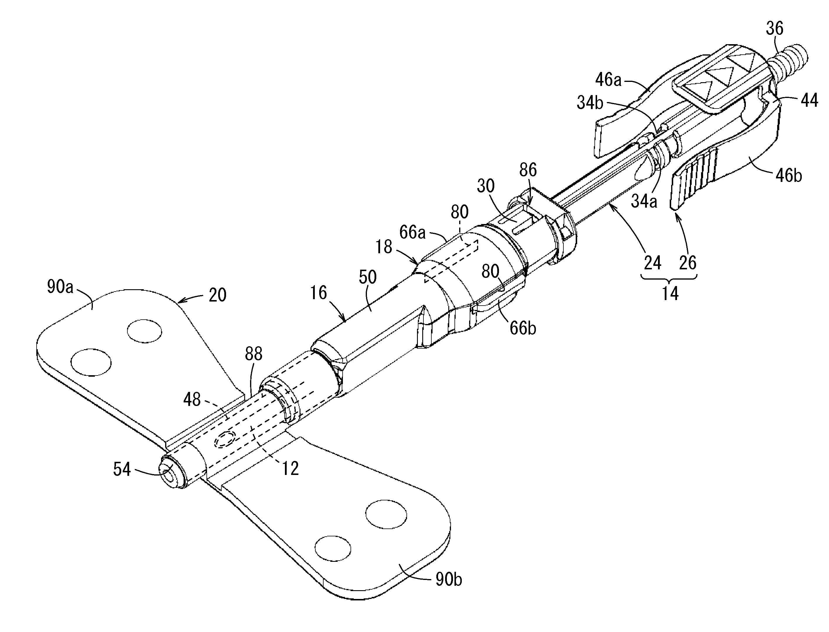
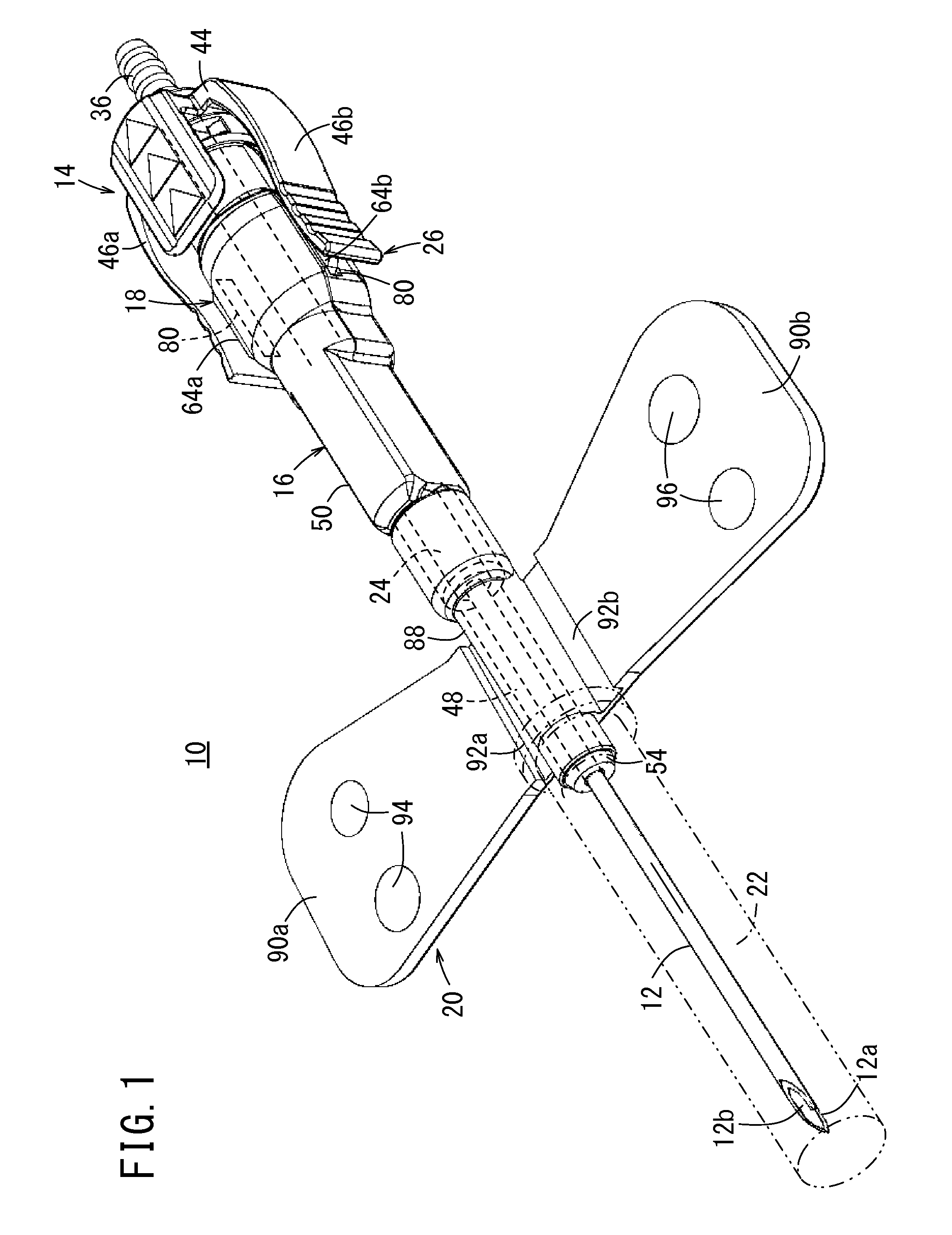
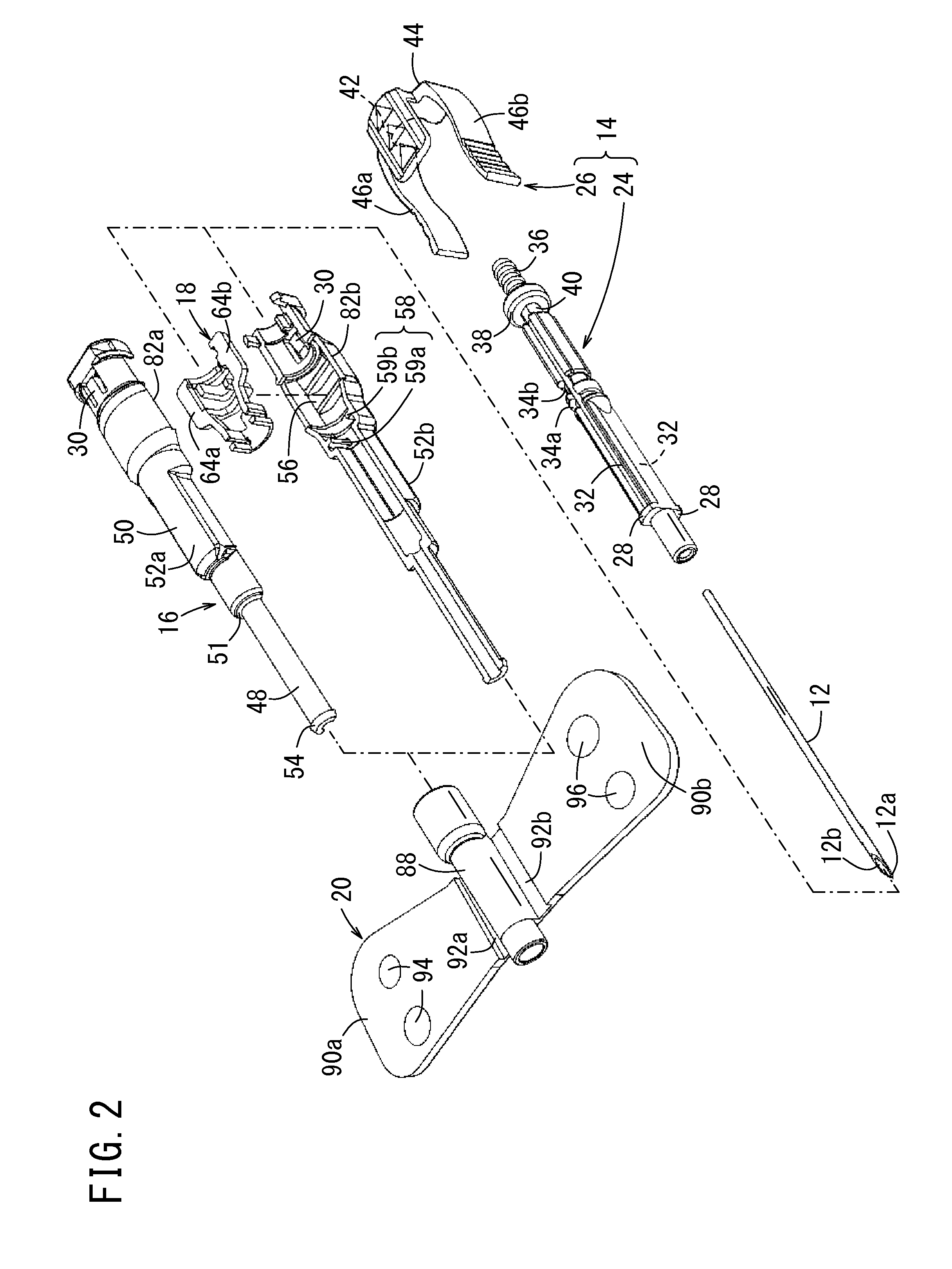
[0037]FIG. 1 is an overall perspective view of the structure of a medical needle 10 according to an embodiment of the present invention. FIG. 2 is an exploded perspective view of the medical needle 10.

[0038]In the present embodiment, the medical needle 10 is a winged needle that is used, for example, for blood collection, blood transfusion, fluid infusion while being inserted into the patient's skin and fixed. Note that the present invention is not limited to the winged needle and can be applied to another types of medical needles 10, for example, to an indwelling needle used for a continuous intravenous infusion.

[0039]The medical needle 10 that is formed to be a winged needle includes a needle body 12, a hub 14, a housing pipe 16, a lock member 18, and a wing member 20.

[0040]The needle body 12 ...


PUM


Abstract

A medical needle includes a needle body including a needle tip on a front end of the needle body; a shaft provided on a base end of the needle body; a housing pipe including a first tube, and a second tube; and a lock member that includes at least one engaging unit that is releasably engaged with the shaft, and at least one engagement release unit. The shaft is slidable from a first position at which the front end of the needle body protrudes from the housing pipe by a predetermined length, to a second position at which the front end of the needle body is located in the housing pipe. Engagement of the at least one engaging unit with the shaft is releasable by pressing the at least one engagement release unit inward.

Description

CROSS-REFERENCE TO RELATED APPLICATIONS[0001]This application is a continuation application filed under 35 U.S.C. 111(a) claiming the benefit under 35 U.S.C. §§120 and 365(c) of PCT International Application No. PCT / JP2013 / 055403 filed on Feb. 28, 2013, which is based upon and claims the benefit of priority of Japanese Application No. 2012-063020 filed on Mar. 21, 2012, the entire contents of which are hereby incorporated by reference in their entireties.BACKGROUND[0002]1. Technical Field[0003]The present disclosure relates to a medical needle used, for example, for blood collection, blood transfusion, or fluid infusion.[0004]2. Background Art[0005]A medical needle that is used, for example, for blood collection, blood transfusion, or fluid infusion while being connected, for example, to a blood collection device, a blood transfusion set, or a fluid infusion set of a blood bag or a blood processing circuit (such as an apheresis circuit, or a hemodialysis circuit) is known. The medic...

Claims


Application Information

Patent Timeline
IPC IPC(8): A61B5/15A61M5/158
CPCA61M5/158A61B5/150641A61M5/326A61M5/3243A61M5/3216A61M2005/1586A61M5/3257
Inventor TERASAWA, YUYAOTSU, JUNICHI
Owner TERUMO KK
Why Eureka
Try Eureka