Current Delivery Systems, Apparatuses and Methods

a delivery system and current technology, applied in the field of non-invasive procedures, can solve the problems that various non-invasive procedures such as heating tissue using a water bath or applying surface coolant cannot be reliably controlled to provide the desired effect at a particular depth or region, and various electricity-based procedures lack tissue targeting capabilities, etc., to achieve less heating, generate more heat, and reduce the effect of area

Inactive Publication Date: 2015-01-01
CYNOSURE
View PDF2 Cites 44 Cited by
  • Summary
  • Abstract
  • Description
  • Claims
  • Application Information

AI Technical Summary

Benefits of technology

[0014]One or more embodiments of the disclosure are directed to a current delivery apparatus such as an electromagnetic current displacement (“EMID”) apparatus with external magnetic field coils and injection current expansion electrodes. Embodiments of the apparatus include injection electrodes for temporary fixation to the patient's skin. According to one embodiment, an energy delivery device generates an injection current that ranges from about 50 mA to about 5 A or more in a target tissue region. In one embodiment, the alternating transcutaneous current in the tissue ranges from about 50 mArms to about 5 Arms. External magnetic fields are applied to the skin surface such that lines of magnetic flux pass through the region in which the current originally flows from one or more electrodes. The magnetic fields effectively push the transcutaneous alternating current deeper...

Problems solved by technology

Unfortunately, various non-invasive procedures such as heating tissue using a water bath or applying surface coolant cannot be reliably controlled to pro...

Method used


Image

  • Current Delivery Systems, Apparatuses and Methods
  • Current Delivery Systems, Apparatuses and Methods
  • Current Delivery Systems, Apparatuses and Methods

Examples


embodiment 120

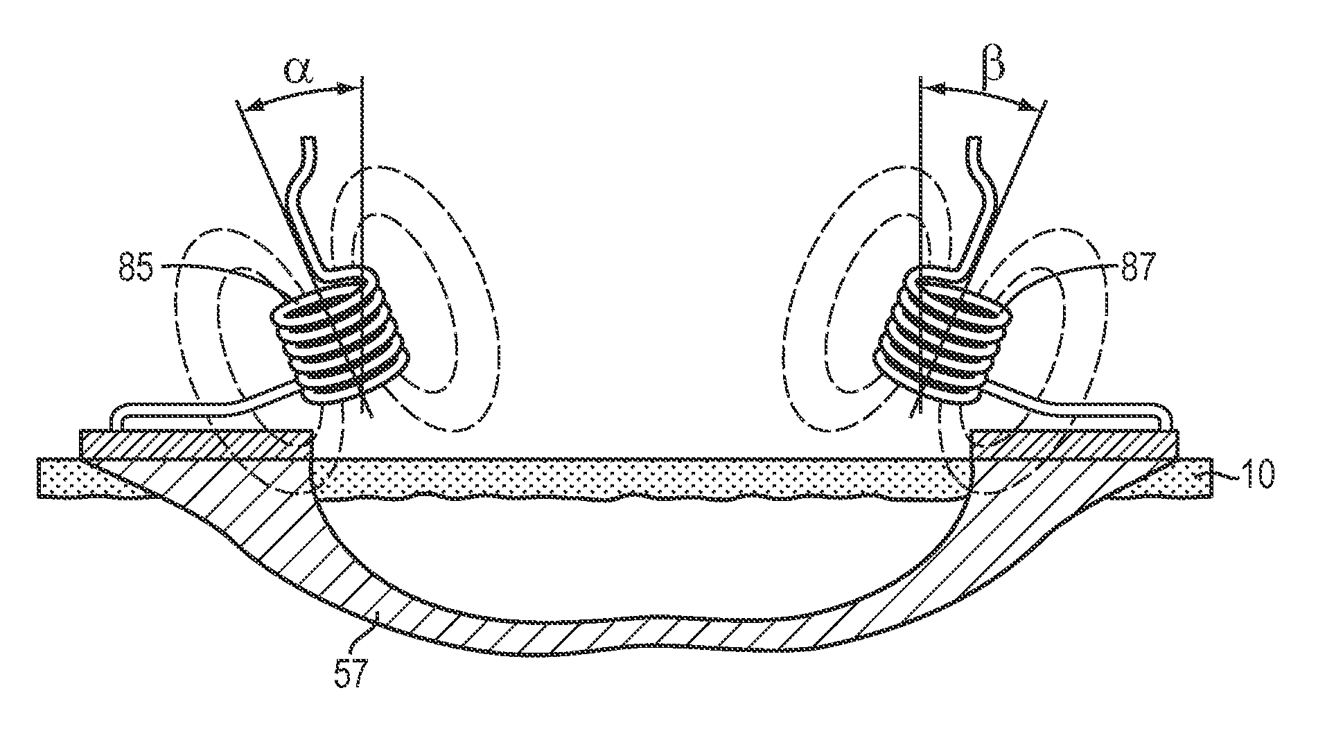
[0065]According to another device embodiment 120, depicted in FIGS. 8A and 8B, one or more insulated static attractors 121, 122 and / or magnetic coils 130, 135, 137 may be arranged parallel to or otherwise disposed on or near the skin surface. The insulated static attractors 121, 122 are used to provide flux cancelling mirror currents on insulated conductor coil to attract the current flow 150 while the magnetic fields of the coils 130, 135, 137 push the current flow deeper. The outer boundary of the magnetic field is shown by dotted regions 140, 145, 162.

[0066]The attractor and coil arrangement of FIG. 8B substantially linearizes current flow along a current channel or otherwise provides lateral stabilization of the current flow. That is, the current can be effectively linearized in a target region of tissue using attractors and magnetic field sources to selectively push and pull along a current channel to promote a substantially linear path. The current channel includes one or more...

embodiment 400

[0069]FIGS. 10A-10B depict a device embodiment 400 of the disclosure utilizing multiple parallel coils and static attractors. FIG. 10A depicts a perspective view of a device 400 in accordance with an embodiment of the disclosure including magnetic coils A, B, and C, two static attractors 415, 417 and a negative 425 and positive 420 electrode. FIG. 10B depicts a side-view where magnetic fields of increasing strength are applied to create a shaped treatment area. According to the illustrative embodiment, coil A outputs a field F1 using a 10 A current, coil B outputs a field F2 using 20 A current and coil C outputs a field F3 40 A current. The varying strength of the fields F1, F2, and F3 creates a free travel zone for electrons 430 and creates a broader area of treatment. The creation of electron travel and exclusion zones using attractors and coils can improve targeted current delivery and thus reduce the number of applications and potential tissue damage arising from over excitation...


PUM


Abstract

In part, the disclosure relates to an electromagnetic current displacement apparatus that includes one or more magnetic field sources and an alternating current source. The apparatus includes current delivery electrodes that may be part of a cuff, a hand held device, or individual electrode pads suitable for temporary fixation to skin. In one embodiment, an alternating current is transcutaneously delivered using skin contacting electrodes sized and arranged to avoid hotspots and provide a uniform delivery of the current. In turn, current attractors and repulsors can be arranged on the skin or in a suitable device to push or pull sections of the current that is disposed below such elements. Magnetic fields can be applied and focused to the regions through which the current passes, effectively pushing the current deeper into a target region below the surface of the skin.

Description

RELATED APPLICATION[0001]This application claims priority to U.S. Provisional Patent Application No. 61 / 782,446 filed on Mar. 14, 2013, the disclosure of which is herein incorporated by reference in its entirety.FIELD OF THE INVENTION[0002]In general, the disclosure relates to the field of non-invasive procedures. More specifically, the disclosure relates to systems, apparatuses and methods for delivering a spatially targeted alternating current to a material such as a tissue.BACKGROUND OF THE INVENTION[0003]Various treatment and aesthetic procedures have grown in popularity for tissue treatments to promote health and improve appearances. These procedures are based upon various technologies such as lasers, focused ultrasound, selective cryolysis, radiofrequency devices, and electrosurgical devices.[0004]Electrosurgical (“ES”) devices are often used for cutting and other invasive procedures such as those described in United States Patent Applications 20130035688, 20130030429, 2013006...

Claims


Application Information

Patent Timeline
IPC IPC(8): A61B18/14H05B6/04
CPCA61B18/1402H05B6/04A61B2018/00577A61B2018/00452A61B2018/0047A61B2018/00005A61B2018/00642A61B2018/00869A61B18/1206A61B2018/126A61N2/02A61B18/14A61B2018/0075
Inventor WELCHES, RICHARD SHAUNHOHM, DANIEL
Owner CYNOSURE
Why Eureka
Try Eureka