System and Methods for Non-Parametric Technique Based Geolocation and Cognitive Sensor Activation

Active Publication Date: 2015-01-08
ROCKWELL COLLINS INC
View PDF9 Cites 32 Cited by
  • Summary
  • Abstract
  • Description
  • Claims
  • Application Information

AI Technical Summary

Benefits of technology

[0011]In another objective, the present invention provides a method for high resolution multiple emitter geolocation in a multi-path environment by utilizing a non-parametric Bayesian clustering technique with a hybrid geolocation technique like AOA-TDOA. The exemplary method comprises the steps of receiving multi-path signals arising from one or more emitters on the antenna array at one or more sensors within the multi-path environment; determining the AOA and TOA data of each multi-path component; executing a non-parametric Bayesian technique to cluster or, in other words, correctly assigning the multi-path contributions to each emitter within the mixture of received signals arising from one or more emitter; transmitting said cluster to a central node by each of the sensors for further processing; estimating the TDOA profile and extracting the AOA data for each individual emitter from within the distinct clusters; and processing by the central node, the AOA-TDOA information for each of the discriminated

Problems solved by technology

However, even hybrid techniques, for example the AOA-TDOA estimation, pose unique challenges when used in multi-path environments like urban areas.
But, the urban area multi-path environment is highly time varying and heavily cluttered giving rise to significant multi-path fading.
In the absence of line-of-sight, the triangulation approach to position estimation does not work effectively.
Consequently, most of the conventional and hybrid geolocation techniques fail to deliver an accurate estimate on the emitter location.
In addition to the above mentioned problem on NLOS conditions and multi-path fading,

Method used


Image

  • System and Methods for Non-Parametric Technique Based Geolocation and Cognitive Sensor Activation
  • System and Methods for Non-Parametric Technique Based Geolocation and Cognitive Sensor Activation
  • System and Methods for Non-Parametric Technique Based Geolocation and Cognitive Sensor Activation

Examples


Example

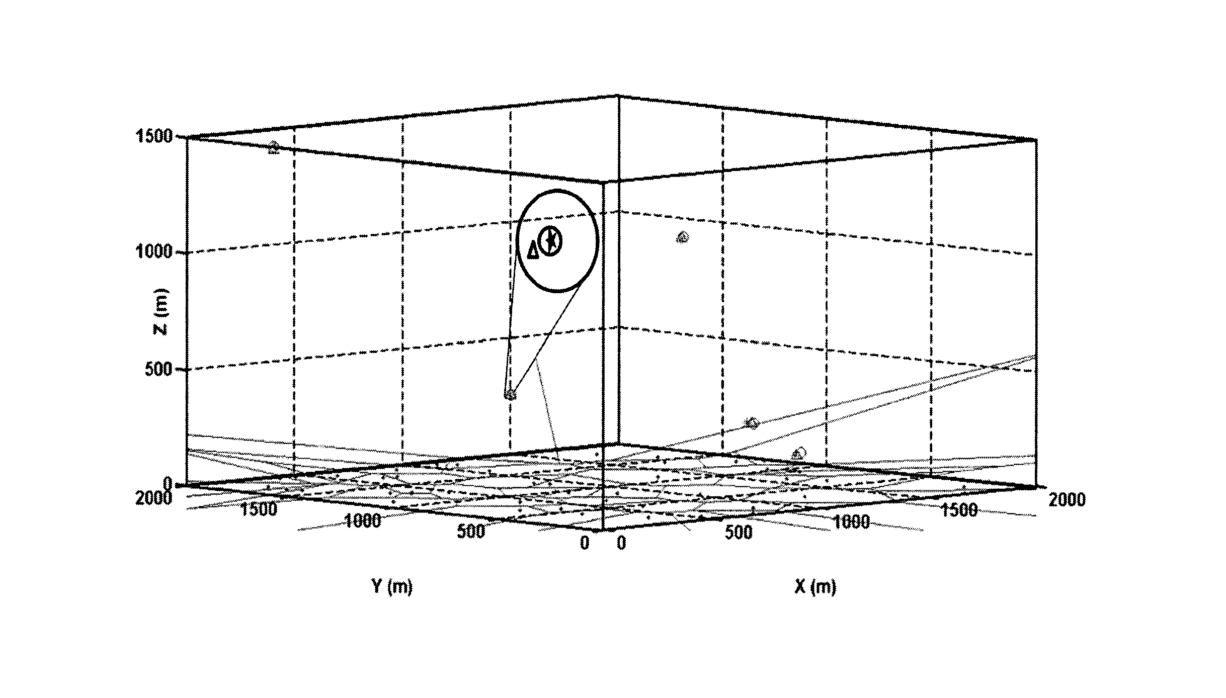
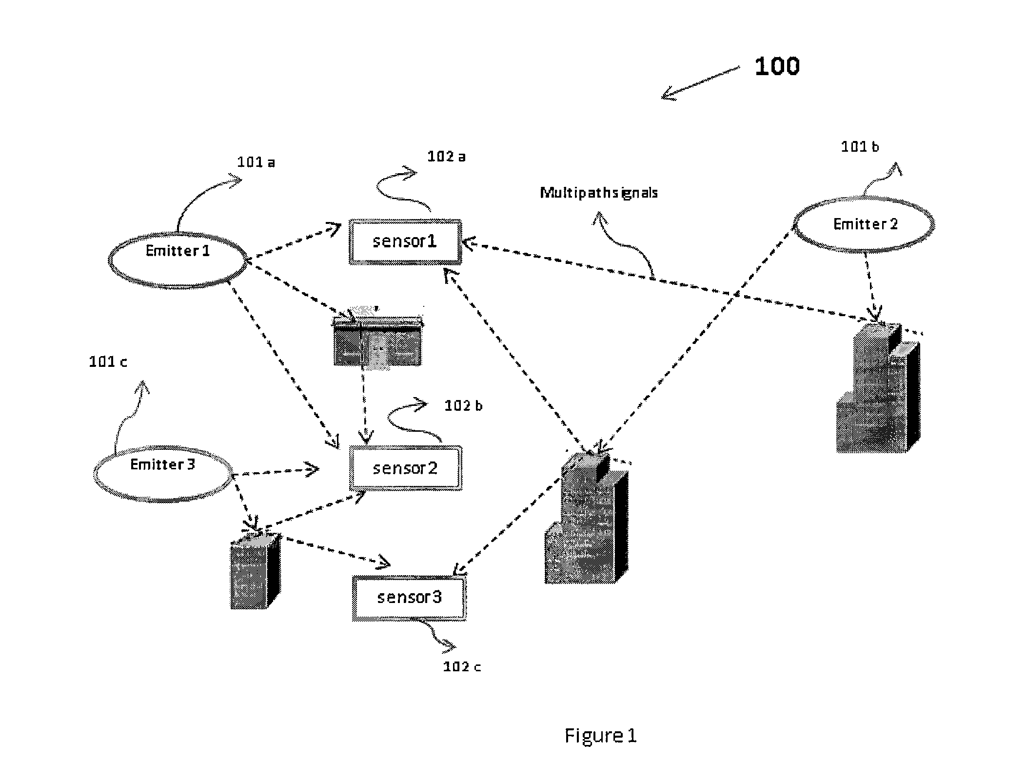
[0022]FIG. 1 illustrates an exemplary multi-path environment (100) like an urban area with one or more emitters (101a, 101b, 101c) located at various sites of the environment. One or more sensors (102a, 102b, 102c) are deployed at various locations within the environment for sensing the signals received from the one or more emitters. Invariably, due to the urban topology there exists non-line-of-sight (NLOS) conditions and severe multi-path fading due to signal reflection from buildings, objects, walls, cars, etc. Due to the NLOS between the emitters and sensors, the signal from one or more emitters reaches the sensors from multiple directions after reflections from obstacles in the cluttered environment. This results in the sensors (102a, 102b, 102c) receiving multiple components of a signal transmitted by one or more emitters (101a, 101b, 101c).

[0023]Referring to FIG. 2, in a preferred embodiment, a sensor (202a . . . 202n) comprises an antenna array (203) arranged to receive mult...


PUM


Abstract

The present invention relates to a geolocation system and method for a multi-path environment. The geolocation system comprises one or more emitters (201a . . . 201n), one or more sensors (202a . . . 202n) comprising at least one processor. A first processor (204) estimates angle of arrival (AOA) and time of arrival (TOA) from the signals received from said one or more emitters (201a . . . 201n). A second processor (205) determines clusters based on the (AOA) and (TOA) data. The system also comprises a central node (207) in communication with at least one sensor (202a . . . 202n) and configured to estimate geolocation of one or more emitters (201a . . . 201n) wherein, said second processor (205) clusters data for the one or more emitters (201a . . . 201n) by executing a non-parametric Bayesian technique and said central node (207) utilizes hybrid angle of arrival-time difference of arrival (AOA-TDOA) technique to determine geolocation of each of the emitters (201a . . . 201n).

Description

[0001]This application claims priority to Indian Application No. 2039 / DEL / 2013 entitled “SYSTEM AND METHODS FOR NON-PARAMETRIC TECHNIQUE BASED GEOLOCATION AND COGNITIVE SENSOR ACTIVATION” filed on Jul. 8, 2013, the content of which are incorporated herein by reference in its entirety.FIELD OF THE INVENTION[0002]The present invention relates to a system and methods for improved geolocation of radio emitters in a multi-path-rich wireless environment. Particularly, the invention relates to the use of a non-parametric Bayesian framework for clustering the Angle of Arrival (AOA) and Time of Arrival (TOA) data from multi-path components to facilitate radio emitter discrimination from the received signal in a harsh multi-path environment.BACKGROUND OF THE INVENTION[0003]Geolocation is the determination of the geographic location of an object through the use of electromagnetic signals, digital mapping, image processing techniques or other data fusion methods aided by electronic communicatio...

Claims


Application Information

Patent Timeline
IPC IPC(8): G01S3/14
CPCG01S3/14G01S5/0278G01S5/28G01S5/0218
Inventor NIJSURE, YOGESH ANIL
Owner ROCKWELL COLLINS INC
Why Eureka
Try Eureka